The Vocia Auxiliary Microphone 1 (VAM-1) is an independent microphone assembly that functions as a slave device to the Vocia Wall and Desk Station (WS-4/10 and DS-4/10) series microphones and to the Vocia Input 6 (VI-6) via the Paging Ports. Up to four VAM-1 slave microphones can be connected per VI-6. The VAM-1 incorporates a PTT switch and has LED indication of the Wait, Talk Now and Unavailable paging states. The microphone latch is magnetic for easy docking to the cradle. Power is provided by the host device.
VAM-1 with Remote Control mode Remote Control is not a supported mode for use with the VAM-1. If selected, the VAM-1 will NOT function correctly.
VAM-1 with Auxiliary Microphone mode will allow for a mic/line audio input, Zone and Paging status LED output indication, external Push-to-Talk connection, 12V DC out supply as well as power indication on the unit itself.
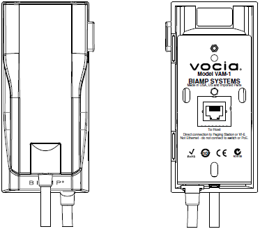
The VAM-1 is designed to be connected directly to a Vocia Paging Station Auxiliary Port or a VI-6 paging port. The VAM-1 has a female RJ-45 connector that faces the rear mounting plate. A screened CAT5e or CAT6 cable wired straight through must be used, up to a maximum of 100 feet (30 meters) distance. Unscreened cable must not be used. The VAM-1 is not an IP device and must not be connected to an Ethernet switch or Network. It must only be connected directly to either a Vocia Paging Station Auxiliary Port or a Vocia VI-6 Paging Port.
The cable connection between the VAM-1 and the host device is monitored and if connection is lost a communication error is reported to the Vocia system by the host. The Audio path between the VAM-1 and the host device is not monitored and therefore a VAM-1 may not be suitable for critical paging applications. A VAM-1 must not be deployed with Emergency paging stations in EN54-16 installations.
See the VAM-1 Wiring Topologies section for example connections to host devices.
The VAM-1 has two bi-color status LEDs visible when the microphone is lifted from the cradle. When connected to a Paging Station the LEDs behave in the following manner:
|
VAM-1 Status |
Busy LED |
Talk LED |
Paging Station LCD Message |
|
Idle |
Green Pulse |
Green Pulse |
Current Page Code |
|
Paging Station in Use |
Red Flash |
Red Flash |
Current Page Code |
|
Paging Station PIN Locked |
Red Flash |
Red Flash |
Station is Locked |
|
Page Setup in Progress - Please Wait |
Yellow |
Off |
VAM-1 In Use |
|
Destination Zones Unavailable |
Red Flash |
Red Flash |
VAM-1 In Use |
|
Please Talk Now |
Off |
Green |
VAM-1 In Use |
|
Approaching End of Maximum Page Length |
Off |
Slow Green Flash |
VAM-1 In Use |
|
Message Playback Request Queued |
Off |
Green Flash |
VAM-1 In Use |
|
Message Playback Request Failed |
Red Flash |
Red Flash |
VAM-1 In Use |
When the VI-6 audio input path is configured to use the VAM-1 the associated line inputs of the VI-6 will be unavailable for use. One VAM-1 is able to be connected to each Paging Port Input with a total of four able to be connected to a single VI-6. The Audio Channel Signal Presence LEDs on the front of the VI-6 chassis will continue to operate when the input channel is configured for Paging. The LEDs will function regardless of whether an associated VAM-1’s PTT is pressed.
The VAM-1 has two bi-color status LEDs visible when the microphone is lifted from the cradle. When connected to a VI-6 they behave in the following manner:
|
VAM-1 Status |
Busy LED |
Talk LED |
|
Idle |
Green Pulse |
Green Pulse |
|
Page Setup in Progress - Please Wait |
Yellow |
Off |
|
Destination Zones Unavailable |
Red Flash |
Red Flash |
|
Please Talk Now |
Off |
Green |
|
Approaching End of Maximum Page Length |
Off |
Green Slow Flash |
|
Message Playback Request Queued |
Off |
Green Flash |
|
Message Playback Request Failed |
Red Flash |
Red Flash |