This section is provided to aid in the use of the VA-2060 and VA-4030 series amplifiers. Please see the Amplifier Hardware Manual for further information on installation of the device.
Note: Sales of the VA-2060 and VA-4030 were discontinued in June 2024.
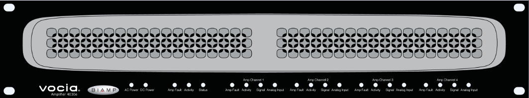
The LED indicators on the front panel of the amplifier provide information and operational status of the amplifier and its associated output and input channels. LED layout and features vary between amplifier models. The LED indicators are placed in blocks and read from left to right when looking at the front of the amplifier. Channel indication LEDs are grouped consecutively from left to right when looking at the front of the unit.
Vocia VA-4030e model shown
AC power A green LED indicator will illuminate when a Mains supply is applied to the unit.
DC Power (VA-2060e, VA-2060se, VA-4030e and VA-4030se models only) - A green LED indicates that 24V DC supply is applied to the unit via either or both 24V Auxiliary power inputs.
Amp Fault An amber LED illuminates when a chassis fault has occurred.
Flashing Amber LED - Warning -the amplifier chassis is not operating within normal limits.
Solid Amber LED – Fault - the amplifier chassis has failed - audio may have stopped.
Activity indicates the configuration status of the Amplifier.
Green LED - the unit is configured
Flashing Amber LED – the unit is active but has no configuration
Amber LED - the unit is configured as a redundant device in a failover configuration.
Red LED - indicates a configuration load failure.
Status indicates the health of the amplifier hardware.
Green LED - indicates that the unit powered up normally.
Amber Flashing LED - shown briefly during the power-up self test
Red LED - the unit experienced a problem during the power-on self test.
Amp Fault -illuminates when an amplifier fault has occurred.
Flashing Amber LED - Warning - the amplifier channel is not performing within normal limits.
Solid Yellow LED – Fault - the amplifier channel has failed, audio may have stopped.
Activity -illuminates when the channel is configured
Green LED – actively passing audio.
Amber LED- channel is acting as a standby channel for failover applications.
Signal -illuminates when the amplifier output channel is configured and passing audio
Green LED - passing audio within operational limits
Amber LED - channel is acting as a standby channel for failover applications
Analog Input (VA-2060e, VA-2060se, VA-4030e and VA-4030se amplifiers only) - indicates audio signal presence on the amplifier input channel.
Green LED - audio signal level is between -36 dBFS and -6 dBFS
Amber LED– audio signal level between -6dBFS and -2 dBFS
Red LED - audio clipping (above -2dBFS)
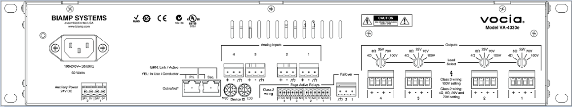
Vocia VA-4030e model shown
Conventions - All numbered audio, relay and power connectors on the rear panel of the amplifier are configured with the lowest output or input on the right of the connector as viewed from the rear of the unit.
Network Connections - The CobraNet network connection is configured with the primary connector on the left and the secondary (redundant) connector on the right as viewed from the rear of the unit. The primary and secondary CobraNet ports are provided to facilitate connection redundancy. Each connector has two associated LEDs that indicate Ethernet link and network activity (see table below).
| Left LED | Right LED | Description |
| None | None | No power or data connectivity. Please check the Device power and network connection. |
| Amber | Flashing Green | Link established and CobraNet activity detected; the unit is acting as a CobraNet performer. |
| Flashing Amber | Flashing Green | Link established and CobraNet activity detected; the unit is operating as a CobraNet conductor. |
| Off | Flashing Green | Failover connection standing by in case the Primary connection fails. By default will be the right Hand socket (Secondary). |
| Flashing Amber | None | CobraNet fault. Check cabling and configuration for errors. |
AC Power Socket - provides for connection of the AC mains power supply via an appropriate power cord (included with unit). The amplifier includes a switch mode power supply with an operating voltage of 100-240V at 50/60 Hz.
Auxiliary Power - Only available with VA-2060e, VA-2060se, VA-4030e and VA-4030se amplifiers – allows the use of a dual 24V DC power input. Note that a 24V DC source must be connected to both DC inputs otherwise the unit will interpret this as a Fault. If only a single 24V power source is available it must be wired across both connections otherwise a power supply Fault will still be reported.
Device ID switches -The rotary ID switches allow the unit to be assigned a unique Device ID. The switches are in hexadecimal format. A Device ID must be assigned to the unit for correct operation.
Analog Audio Inputs - Only available with VA-2060e, VA-2060se, VA-4030e and VA-4030se amplifiers - each amplifier channel has an analog input connector that allows a balanced microphone or line source to be selected via software as the background source for the amplifier channel associated with that input only. Two inputs are available on the VA-2060 series amplifiers and four on the VA-4030 amplifiers.
Page Active Relay (PAR) – Each channel has a relay that will engage when paging is active in the channel at or above a priority specified for that PAR in Vocia software. Relay Normally Open (NO) and Normally Closed (NC) contacts are presented on 3.5mm plugable screw block connectors.
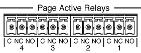
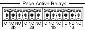
VA-4030 series amplifiers have one PAR relay per channel (left hand Image above). VA-2060 series amplifiers have two PAR relays per channel, operating in tandem (right hand Image above).
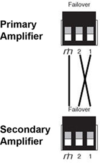
Failover -The Failover connector facilitates redundant Device Failover only (Failover of one amplifier unit to an identical amplifier unit). Wiring is ‘crossed’ as indicated below.
Load Select - The amplifier output is user configurable via the use of a recessed indented selector. The switch is designed to be operated with a flat blade screwdriver. Selections available are 4Ω, 8Ω, 25 Volt, 70 Volt and 100 Volt.
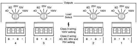
Speaker Output Connection - Used to connect loudspeakers.
To facilitate parallel wiring, each connector allows for the connection of two loads to each amplifier channel. Two four-way connectors are available on to VA-2060 series and four on the VA-4030 series amplifiers.
The total load impedance applied to a speaker output must not be lower than the nominal impedance selected for the channel on the Load Select switch. For 25V, 70V and 100V outputs minimum load impedances are indicated.
|
|
VA-4030 Series Amplifiers |
VA-2060 Series Amplifiers |
|
25 Volt |
21 Ω |
11 Ω |
|
70 Volt |
163 Ω |
82 Ω |
|
100 Volt |
330 Ω |
167 Ω |
The Amplifier monitors faults on speaker connections using a combination multiple out-of-band (inaudible) high frequency tones for end-of-line detection. For end-of-line detection, one or more (up to 15 maximum) ELD-1 units must be connected to the end/s of the speaker line. End-of-line and ground fault detection may be individually enabled/disabled in the Vocia software. To prevent the possibility of interference with these monitored tones;
When a fault is detected on the speaker line or amplifier channel, the lower left LED on the RJ-45 socket will illuminate Amber and remain on until the fault is resolved. Providing a valid PoE power source and Ethernet connectivity is available the ELD-1 the solid amber indicator can be used to physically identify the ELD-1 that is reporting an issue.
If there is a fault with an ELD-1 the ELD-1 Assignment tab in the Amplifiers properties can be used to identify which ELD-1 is reporting the fault condition.