The Voice Alarm (VA) Active Output is provided to allow external indication that the Vocia system has been activated in Emergency mode in response to an Alarm Input. A constant output (pull to ground) denotes that an Emergency message is playing. A pulsed output (pull to ground) (1.25Hz) indicates that an Alarm is active but Emergency messages have been Silenced.
The General Fault (GF) Output is provided to allow external indication that there is a Fault in the Vocia system that could affect delivery of an Emergency Message.
VA and GF Outputs will provide a closure to ground during an active VA or GF event.
For monitoring purposes a load must be connected between each output and a positive voltage source referenced to the CI-1 Ground.
The VRef connection may be used as a voltage source required for monitoring the VA and GF Outputs. This output is current limited at 100mA. An external PSU can also be sourced for this voltage.
The resistors specified are common values for short to mid length runs. If long cable runs are present between the CI-1 and the end of the monitored line, the resistor value may need to be lessened. Resistor value can be verified by measuring the voltage present between the positive voltage source and GF or VA output and ensuring that it is greater that 0.8VDC.
Refer to CI-1, LSI-16 and LSI-16e manuals for more information.
1. Alarm / Fault Output Driving a Relay Powered From a CI-1
The load presented by the relay coil will allow the CI-1 to monitor the line connecting the circuit. Connecting the GF and VA Alarm Outputs in this manner will register an open or short in the connecting wire as a fault.

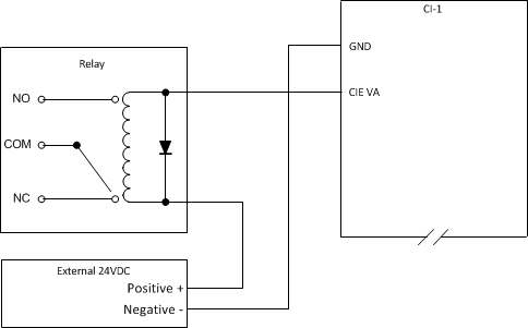
2. Alarm / Fault Output Driving a Relay Powered Externally
The load presented by the relay coil will allow the CI-1 to monitor the line connecting the circuit. Connecting the GF and VA Alarm Outputs in this manner will register an open or short in the connecting wire as a fault.

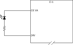
3. Alarm / Fault Output Driving a LED Powered From a CI-1
The load presented by the LED and it’s associated current limiting resistor will allow the CI-1 to monitor the connecting circuit. Connecting the GF and VA Alarm Outputs in this manner will register an open or short in the connecting circuit as a fault. The resistor value required is determined by the current handling characteristics of the LED.

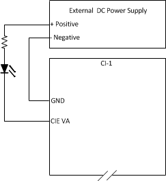
4. Alarm / Fault Output Driving a LED Powered Externally
The load presented by the LED and it’s associated current limiting resistor will allow the CI-1 to monitor the connecting circuit. Connecting the GF and VA Alarm Outputs in this manner will register an open or short in the connecting circuit as a fault. The resistor value required is determined by the current handling characteristics of the LED.

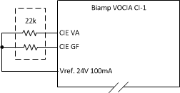
5. Unused Alarm / Fault Outputs
If either of the Alarm/Fault outputs are not used they MUST be terminated as shown. This will indicate to the Vocia system the line is monitored and there is no fault present.

6. Alarm/Fault Outputs Providing a Closure to a Monitoring Device
In this instance the monitoring voltage and required load resistors are introduced at the CI-1 end of the line. Connecting the GF and VA Alarm Outputs in this manner will NOT register an open or short in the connecting wire as a fault. An external power supply could be used in place of the CI-1 Vref.
Resistor values shown are default values and may be required to change. Refer to the Notes section for more information.

7. Alarm/Fault Outputs Providing a Closure to a Monitoring Device (Line Monitored)
In this instance the monitoring voltage and required load resistors are introduced at the end of the line. Connecting the GF and VA Alarm Outputs in this manner will register an open or short in the connecting wire as a fault. An external power supply could be used in place of the CI-1 Vref.
Resistor values shown are default values and may be required to change. Refer to the Notes section for more information.
