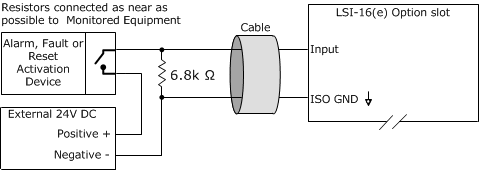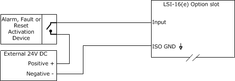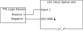
The schematics below details the connection of external equipment to the Vocia LSI-16e IM-16 Module. All connections shown do not include the CI-1.
The IM-16 Module of the LSI-16e allows more connection points for Alarm Activation, Fault Indication, and Zone Alarm Reset. The individual function of each input port is software configurable. The physical connection from the external hardware device to the IM-16 module is the same regardless of the intended input port use. Physical connection schematics are shown on this document.
IM-16 inputs support a Logic Level (software selectable) of High Range Monitored, High Range Un-monitored, TTL and Contact Closure input levels which are configurable in the software.
The Active State selection in Vocia Software indicates the transition needed to trigger the Alarm or Fault event. Action State of High indicates that the event is triggered from a Low to High transition. Action State of Low indicates that the event is triggered from a High to Low transition.
Voltage Ranges:
High Range Low: 0-8VDC
High Range High: 12-30VDC
TTL Low: 0-0.8VDC
TTL High: 2-5VDC
Both Chassis Ground and Isolated Ground are available on the IM-16 connectors. By default, all input circuits are isolated with respect to the LSI-16 ground. Any external input connections must be logic referenced to the Isolated Ground. This configuration allows external equipment to be interconnected to the LSI-16 without ground current interaction between devices. The IM-16 ground appears on a single terminal (Pin 1) on each of the two connector banks (‘Option A’ and ‘Option B’). This should only be used if circuit isolation is not required. The two isolated grounds of the IM-16 board are connected internally. For ease of wiring, every Control Input pair has an Isolated Ground connection adjacent to it.
The 24VDC connection may be used as a voltage source required for monitoring and signaling. This output is current limited at 100mA across all input ports. An external power supply can also be sourced for this voltage.
Refer to LSI-16e manual for more information.
1. High Range Monitored Input – Active High - 24VDC Locally Sourced
Notes: Vocia software configured as High Range Monitored - Active State High. Circuit shown in Low State.

2. High Range Monitored Input – Active High - 24VDC Externally Sourced
Notes: Vocia software configured as High Range Monitored - Active State High. Circuit shown in Low State.

3. High Range Unmonitored Input – Active High - 24VDC Locally Sourced
Notes: Vocia software configured as High Range - Active State High. Circuit shown in Low State.

4. High Range Unmonitored Input – Active High - 24VDC Externally Sourced
Notes: Vocia software configured as High Range - Active State High. Circuit shown in Low State.

5. Input - 5V TTL Logic Control

Notes:
• Low Voltage = 0 – 0.8 VDC. Logic High = 2 – 5VDC.
• If configured as Active State High Alarm/Fault/Reset triggers when voltage transitions from Low to High.
• If configured as Active State Low Alarm/Fault/Rest triggers when voltage transitions from High to Low.
6. Contact Closure Mode
