Sixteen Control Inputs are provided on the GPIO-1. The inputs support both 24V, TTL and Contact Closure input levels which are configurable in the software. An input configured for 24V logic will be able to be monitored for the presence of a terminating resistor to detect open circuit faults. See the GPIO-1 Hardware section for more details on hardware functionality.
Inputs are discrete, meaning only one Control Input Event can be assigned to a physical input at a time.
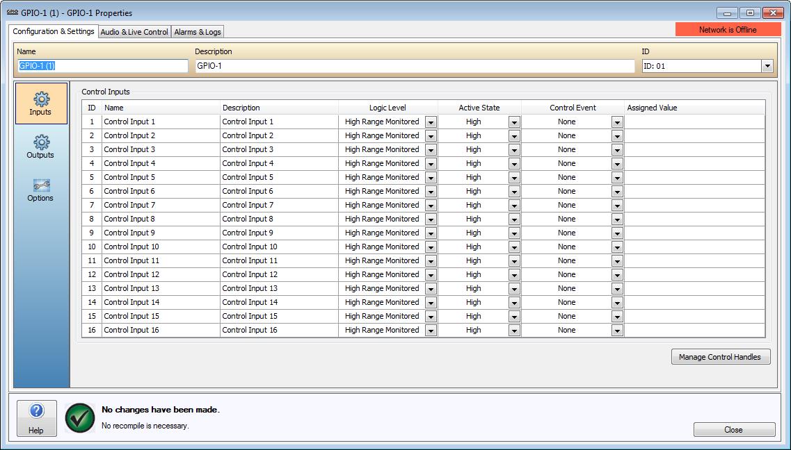
The Name and Description columns allow users to associate each of the four Input and Output channels with the physical input and output configuration of the device.
The Logic Level column specifies the required logic level trigger to assert an input.
High Range - This selection will cause the GPIO input to look for the input to switch from a voltage of 24V DC to Isolated Ground. This can be configured in software to detect a low to high or high to low transition by the Active State selection in the following column.
High Range Monitored - This selection will cause the GPIO to look for a low to high current transition to activate while connected to a monitored 24V circuit.
TTL logic level - This selection will cause the GPIO input to look for a transition between 2V and 5V TTL to be activated. The Active State selection will determine whether this is a low to high or a high to low transition.
Contact Closure - This selection allows the inputs to be asserted without a monitoring resistor or voltage. Line monitoring of a Contact Closure input is not possible.
Please review the GPIO-1 Wiring Inputs section for physical connection details.
An Active State can be specified. This can be configured as a High, Low, Toggle High and Toggle Low trigger. A Lower Threshold and Upper Threshold can also be specified.
The Control Event field can be used to select a Control Handle, Page Code, User Input, System Mute, Zone State, Emergency Fault, Emergency Zone Alarm or Emergency Zone Reset Control Event.
The Assigned Value field can be used to configure additional options for the selected Control Event.
The following Control Input Events are supported;
Control Handle - Changing one or more Control Outputs.
System Mute - Activating or deactivating System Mute.
User Audio Input - Activating or deactivating a User Audio Input on a VI-6.
Page Code - Triggering a single Pre-Recorded Page Code to be played by an MS-1.
Zone State - Setting the Background Source, Volume, Zone Mute, BGM Mute, Page Inhibit and Allow Page Inhibit states for up to 10 Zones.
In addition to standard GPIO-1 Control Input Events, if the World contains a Life Safety Interface 16e (LSI-16e) then the GPIO-1 can be configured to assert and control the Emergency system. The inputs can be configured to control the following Emergency Input Events;
Emergency Fault Input - Indicates a fault in a PSU, transmission path, Ethernet interface or protection mechanism. The Alarm will be reported via the LSI-16e.
Emergency Alarm Input - Indicates an Alarm condition in an Emergency Zone. The LSI-16 will indicate the Zone Alarm condition and place the Emergency Zone into the state specified by the input configuration.
Emergency Zone Reset Input - Reset a specified Emergency Zone to the idle state. The GPIO-1 will instruct the LSI-16e to return the specified Emergency Zone to the idle state.
For further details on Control Input Events, please refer to the Control Input Events section.