This section is provided to aid in the use of the GPIO-1. Please see the GPIO-1 Manual for further information on installation of the device.
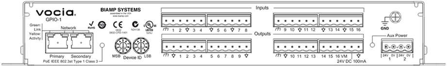
The GPIO-1 provides sixteen general purpose logic inputs and sixteen general purpose outputs to control various aspects the system. The GPIO-1 is a monitored device and can be used in life safety applications where more logic inputs or outputs are required. Please review the Control Input Events and Control Output Events section for more details.
The GPIO-1 has two RJ-45 connectors located on the rear panel that enable redundant network wiring.
| Left LED | Right LED | Description |
| None | None | No power or data connectivity. Please check the Device power and network connection. |
| Amber | Flashing Green | Link established and CobraNet activity detected; the unit is acting as a CobraNet performer. |
| Flashing Amber | Flashing Green | Link established and CobraNet activity detected; the unit is operating as a CobraNet conductor. |
| Off | Flashing Green | Failover connection standing by in case the Primary connection fails. By default will be the right Hand socket (Secondary). |
| Flashing Amber | None | CobraNet fault. Check cabling and configuration for errors. |
A green power LED is provided which illuminates when PoE power is applied to the unit via the Network ports. The same goes for the Aux Power input indicator. If PoE Power is required an 802.3at Type 1, Class 3, compliant PoE switch or mid-span adapter is required to either or both network inputs.
The Vocia GPIO-1 is capable of operation from two power supply types - PoE and 24VDC. Any or all power sources may be connected concurrently. Loss or return of any power supply will not result in interruption to normal operation. Monitoring of all power sources is selectable via the Vocia Software in the GPIO-1 Options dialog. If connected PoE has priority over 24V DC.
The GPIO-1 uses comprehensive self-monitoring and is capable reporting any detected faults to the system. Refer to the Alarm & Logs section for further information.
Sixteen parallel input connections are provided on the GPIO-1 as well as Isolated Ground and Chassis Ground connections. Under software control the logic level of each input can be set independently to operate in the following ways;
Please refer to the Wiring GPIO-1 Inputs section for wiring schematics.
Sixteen parallel outputs are provided on the GPIO-1 as well as Isolated and Chassis Ground connections. Each output is able to accept either an external positive voltage between 4 and 30V or use the 24V DC 100mA reference voltage provided on the unit. Outputs will be monitored for open circuit, short to ground and short to supply. A Voltage Monitor (VM) input is provided in order that a short to supply reference voltage is incorporated in output fault monitoring. A voltage of between 4-30V is required by the VM Input in order for the Outputs to operate. If the GPIO-1 Outputs are using a Monitored type of circuit the VM input must match or be greater than the highest Output Voltage being used. If a higher Voltage is seen on the Outputs compared to the VM Input a Short to Supply fault will be indicated.
Please refer to the Wiring GPIO-1 Outputs section for wiring schematics.