When enabled, the VA-8600 will monitor each channel for fault conditions on the speaker line.
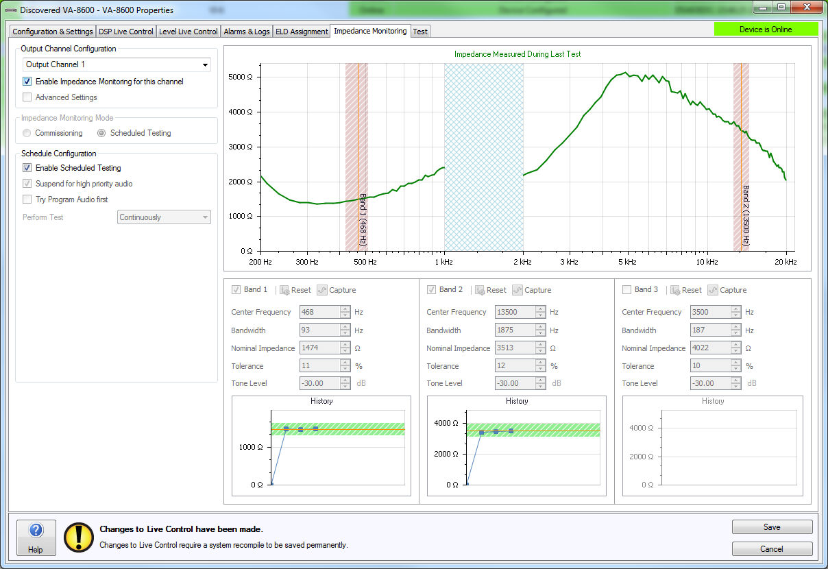
A real-time impedance versus frequency curve is generated to characterize the speaker line. If the impedance readings fall below or above the configured thresholds a fault is reported. Up to three frequency bands per channel can be monitored.
In order to achieve usable results and/or characterize the line there must audio playing through the card at a sufficient level. Typically higher levels allow for more precise frequency plots and therefore more consistent fault detection. The audio must contain frequency components in the configured bands of interest. To facilitate this, the system can be configured to periodically generate tones or pink noise. A tone generator, pink noise generator or regular program audio can be used for analyzing and characterizing the normal operation versus a fault condition.
A line graph will plot the measured impedance of the speaker line data. Frequency values between 1kHz and 2kHz are prevented from being used as impedance values measured in this area may be unreliable.
Output Channel - Selects the channel that impedance monitoring is being configured for.
Enable Impedance Monitoring for this channel - determines if impedance monitoring is on or off for the selected channel.
Advanced Settings - Enables the Advanced Settings field where the average sample length can be specified. The average sample length defines the number of impedance measurements that are collected and averaged to determine the load impedance curve.
Commissioning - Enables options that assist the impedance monitoring configuration at the time of setup. During commissioning ELD-1 devices should be disabled or false alarms on these channels should be disregarded. PLD-1 devices should remain enabled and connected.
Scheduled Testing - Enables the scheduled testing of the configured values defined in the commissioning stage.
Manual - The speaker line is able to be characterized during commissioning using the stimulus source which is one of either the Program Audio (i.e. background music and paging audio), a single Pink Noise Generator, or using Tone Generators which are designed to provide audio content in each of the three monitoring bands that can be configured. It is possible to Duck, Mute or Mix the background audio using either the Pink Noise Generator or Tone Generator as necessary. The level of Pink Noise and the Tone Generators will be live controllable using a Level spin control.
Start Stimulus - Begins the speaker line characterization using the values configured in the Stimulus Settings section to excite the line.
Assisted - By using a monitoring algorithm the Assisted characterization conducts a sweep of the speaker line then chooses up to three of the most reliable monitoring bands and configures their settings accordingly. If the algorithm does not determine other frequencies to be stable enough for an accurate reading it may choose to only use one or two bands. It is highly recommended to use the assisted setting unless a comprehensive knowledge of impedance monitoring and its configuration is known.
Start Auto Characterization - The first step in the Auto Characterization process is a dialog asking what sort of speaker type is connected to the channel. Due to the complex nature of the impedance of a speaker line that consists of several different speaker types, Auto Characterization will only support speaker lines of a single type of speaker. The four kinds of speaker types that the algorithm supports are:
One Way Speaker Ported Enclosure
One Way Speaker Open Baffle
Two Way Speaker Ported Enclosure
Two Way Speaker Open Baffle
Horn
The measured impedance data is processed using one of several algorithms depending on the speaker type selected from this list.
The next screen allows the level of Pink Noise used to excite the speaker line in order for the amplifier to be able to take a measurement of the speaker line impedance to be adjusted. Once the level of Pink Noise has been set correctly the test can be begin by clicking the “Start” button. During the test any change made to the level of the Pink Noise Generator will cause the test to be restarted. The Pink Noise level used during this Auto Characterization will be the level used for all subsequent tests.
During the measurement process the progress bar will display the convergence of the impedance monitoring algorithm. Once the convergence reaches 100%, the Pink Noise Generator will be switched off and the Vocia software will analyze and process the results of the test. If the user started the Auto Characterization process with a stimulus source of Pink Noise Generator then the process is now complete. If the stimulus source is a tone generator, after the pink noise stage the tone stimulus will play in order to check for any variance in the impedance under tone stimulus versus pink noise stimulus.
If the stimulus level is too low the convergence will never reach 100%. To determine how long the measurement is running the elapsed time of the measurement will be shown. With the information of the time and convergence status it is possible to determine if the stimulus level needs to be set higher. The ‘Cancel’ button will immediately close the ‘Impedance Monitoring Result’ dialog and no Monitoring Band settings will be configured.
Once the Auto Characterization is performed successfully the progress dialog will disappear and the ‘Impedance Measurement Result’ plot will be shown. In this dialog the results of the impedance measurement taken are presented. The suggested Monitoring Band settings are displayed on a per-band basis and the recommended values will populate in the band configuration boxes below. After performing a successful Auto Characterization the Impedance Monitoring Mode for that output channel will switched to Scheduled Testing ready for use.
Stimulus is used to define the type of content used to excite the speaker line for the impedance monitoring.
Tone Generator - The tone generator uses the level and frequency values as specified in each monitoring band for testing the speaker line.
Pink Noise Generator - The pink noise generator uses pink noise to excite the speaker line. An option box to specify the level will appear once this option is selected.
Program Audio - Program audio (BGM / Paging / Other) will be used to attempt the mapping of the speaker line impedance. Program audio is whatever signal is present on that channel at the time of testing.
Background Effect
If Suspend For High Priority Audio is disabled, this will not affect Pages above the Page Inhibit Priority Threshold or Emergency Paging announcements
Duck - Will attenuate the level of the regular paging and BGM while mixing in the test audio into the audio mix.
Mute - Will stop regular paging and BGM while playing the test audio.
Mix - Will combine the regular paging and BGM with the test audio so both are heard at the same time.
Enable Band - When enabled the band will be monitored in real time
Reset - Will return all values for the band to their defaults
Capture - Will capture the Nominal Impedance and Tolerance for the monitoring band based on the latest real-time impedance curve, at the specified Centre Frequency over the specified Bandwidth. If the impedance monitoring data is not converged this button will be inactive.
Center Frequency - The specific frequency to be monitored
Bandwidth - The amount of frequency either side of the center frequency that should be monitored
Nominal Impedance - The average impedance of the center frequency and bandwidth
Tolerance - The amount above or below the nominal impedance that when exceeded causes a fault to be reported
Tone Level - The tone level to use when the tone generator is selected
History - a historical record of the last ten average impedance values for the band will be plotted to show variation with time.
When in Scheduled Testing mode all settings in the Band Enablement area will be disabled. If these test values need to be changed the Impedance Monitoring Mode should be switched back to the Commissioning setting.
Enable Scheduled testing - The stimulus and settings configured when in Commissioning Mode will be performed automatically at defined times.
Suspend for high priority audio - Controls whether Impedance Monitoring tests are run when emergency paging, emergency messages and regular paging above the Page Inhibit Priority Threshold is occurring
Try Program Audio first - This setting is only available when Tone Generator or Pink Noise Generator is selected for the stimulus and it allows the impedance monitoring test to try to use program audio to achieve convergence in the first instance. The VA-8600 will turn on the stimulus source if no convergence is possible with the Program audio.
Perform Test - Options to perform the impedance monitoring test include Once Only, Multiple Times Per Day or Continuously.
Days to Perform Testing (not available when Perform Test 'Continuously' is selected) - Selects which days of the week the test should run.
Test Period Start Time (not available when Perform Test 'Continuously' is selected) - Selects what times the test should run on the days of the week selected.
Perform Test Every (only available when Perform Test 'Multiple Times Per Day' is selected) - Allows the interval the impedance test will be re-run to be set.
Test Period End Time (only available when Perform Test 'Multiple Times Per Day' is selected) - Selects what times the testing should stop on the days of the week selected.
If Suspend for high priority audio is enabled, Emergency Paging, Emergency Messages and regular Paging above the Page Inhibit Priority Threshold will take priority over any currently running or scheduled impedance monitoring tests and will play out unaffected by the stimulus sources. As such any pink noise or test tones in progress will be stopped, and any scheduled tests during that period will be deferred until
The audio playback has concluded, and
There has been no further Emergency Paging, Emergency Messages and regular Paging above the Page Inhibit Priority Threshold for 10 seconds.
If multiple tests are deferred, only a single test will occur afterwards. If the test is deferred beyond the Finishing Time, it will be cancelled and recorded in the log but will not raise an Alarm.
Failover will only be triggered by impedance monitoring if the primary card is configured to Enable Monitoring and Impedance Monitoring Fault Triggers Failover and the output channel’s Impedance Monitoring mode is set to Scheduled Testing mode.
Redundant speaker wiring is not supported if Impedance Monitoring is enabled for that channel. The reason for this is to ensure that the same speaker line is being characterized in both failed-over and non-failed-over states. The redundant AM-600 cards must be wired to a common speaker line in parallel, or through a VFOM-1 as appropriate for the failover scheme.
Behavior in the event of failover is as follows:
The primary AM-600 card (that had been driving the speaker line on which the fault was detected) will be shut down.
The secondary AM-600 card will be taken out of standby and switched into the signal chain, with any configuration being applied as necessary to carry on from where the primary left off.
A speaker line fault will be indicated and the failover event logged.
1:1 Channel Failover
Up to four AM-600 cards will carry out impedance monitoring per chassis. Each primary and secondary pair of AM-600 cards must be wired in parallel to a single speaker line.
Only one entry for each pair will appear in the Impedance Monitoring tab (channels 1, 3, 5, 7). The Enable Monitoring will apply to both the primary and secondary AM-600 cards, regardless of whether they are currently enabled or on standby.
3:1 Channel Failover
Up to six AM-600 cards will carry out impedance monitoring per chassis at any one time. The speaker lines must be wired through a VFOM-1 such that the two redundant AM-600 cards can be switched in when needed. Per 4- channel failover block, only three primary channels will appear in the Impedance Monitoring tab (channels 1 to 3, 5 to 7). The Enable Monitoring setting will apply to the AM-600 cards currently switched in to the audio chain.
7:1 Channel Failover
Up to seven AM-600 cards will carry out impedance monitoring per chassis at any one time. The speaker lines must be wired through a VFOM-1 such that the redundant AM-600 card can be switched in when needed. Only the seven primary channels will appear in the Impedance Monitoring tab (channels 1 to 7). The Enable Monitoring setting will apply to the AM-600 cards currently switched in to the audio chain.
Chassis Failover
Up to eight AM-600 cards will carry out impedance monitoring per chassis pair at any one time. Each AM-600 card in the primary chassis must be wired in parallel to the corresponding card in the secondary chassis and on to the associated speaker line. Only one entry for each channel pair will appear in the Impedance Monitoring tab (channels 1 – 8). The Enable Monitoring setting will apply to the AM-600 card currently switched in to the audio chain.