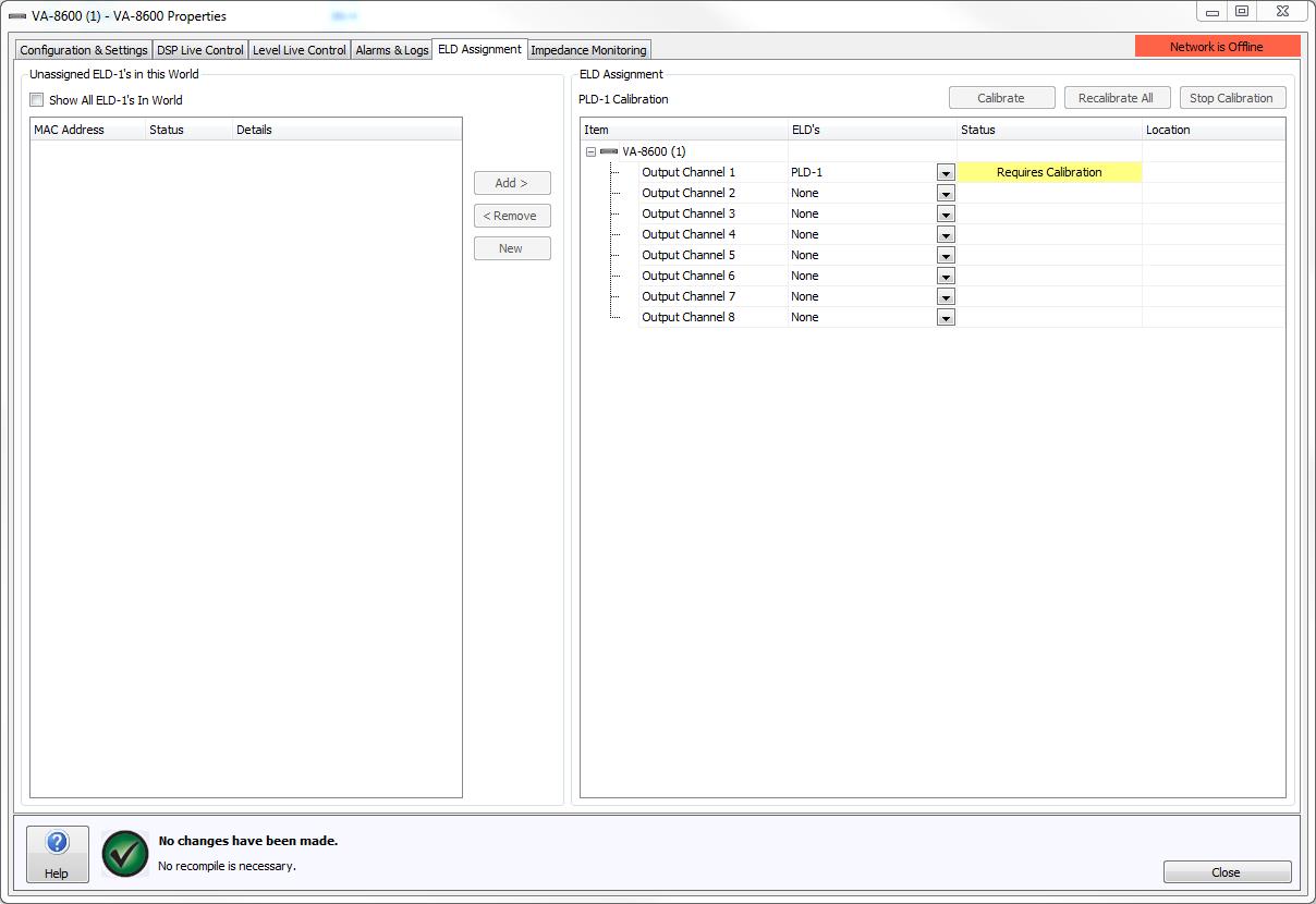
The ELD Assignment tab displays a listing and status of all End of Line Devices (ELD-1) in the local World. A drop down menu is provided to select what sort of monitoring device will be used, if any. Options include None, ELD-1's, PLD-1 or Pilot Tone.
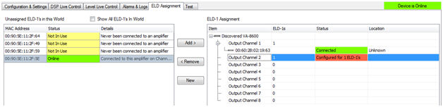
By default, the left section of the dialog box shows Unassigned ELD-1’s in this World. A checkbox is provided that will Show All ELD-1's in World, this can be useful during troubleshooting as it shows all ELD-1 devices that are currently discoverable in the World.
All ELD-1's shown in this section will list their MAC Address, Status and Details.
MAC Address: A unique identifier used to distinguish devices on the network. The MAC Address is also indicated on the outside of the physical ELD-1
The Status column will indicate the current state of any ELD-1s
Red - Fault detected – Confirm speaker cabling is correct.
Yellow – Not in use – Not physically connected/associated with an amplifier or output channel.
Green – Online – Review Details column for information on the connected amplifier or output channel.
The Details column will indicate additional information about the ELD-1. Messages include:
Never been connected to the amplifier.
The output device and the channel it was last associated with.
The output device and channel it is currently associated with.
The central divider has control buttons to Add, Remove and assign New ELD-1's.
The right hand ELD-1 Assignment section relates to the current output device and shows the ELD-1 channel assignment. If Device Failover is configured, both devices in the failover configuration are listed. For correct feedback of current settings the user is required to be Online.
The Item column indicates the output channels and the MAC Address's of any ELD-1’s assigned to them.
The ELD-1s column is used to specify the number of ELD-1s that the output device is expecting on the associated channel. The PLD column is used to specify whether a PLD-1 is expected on the associated channel or not. The corresponding Status field will indicate the current state of any assigned device. Note that an amplifier can be configured to use Vocia ELD-1's, or a Vocia PLD device to monitor the integrity of the speaker line, but not both (on the same channel). A mixture of ELD-1's and PLD devices across multiple outputs however on the same chassis is permissible.
ELD-1 Status
Red – Fault Detected -The specified number of ELD-1s for the channel is incorrect, the ELD-1s are offline or there is a problem with the speaker cable. Refer to the Alarms & Logs tab to troubleshoot the cause of the fault.
Yellow - Warning - ELD-1 association has not been configured or detected correctly.
Green – Connected – ELD-1’s have been associated correctly and no problems with the speaker line have been detected.
PLD Status
| Status | System | Color | Description |
| Requires Calibration | Online / Offline | Yellow | PLD requires calibration on this channel. |
| Detecting | Online | White | The amplifier is applying pink noise over the PLD frequencies to determine the PLD center frequency notch. |
| Calibrating | Online | White | PLD calibration is being performed. |
| Calibrated | Online / Offline | White | The PLD was calibrated correctly. |
| PLD Detection Failed | Online / Offline | Red | The PLD detection or calibration process failed. |
| Connected | Online | Green | The PLD has been detected on the speaker line. |
| Channel Failure | Online | Red | The PLD couldn't be found on the speaker line. |
To aid troubleshooting, the Location field can be used to specify a name and details of the physical device.
If an ELD-1 assigned to an output channel needs to be assigned to a different channel, select the ELD-1 and 'drag and drop' it to the new output channel, alternatively use the Remove then the Add control button on the central divider.
PLD’s can be enabled on a per channel basis. Configuration of a PLD device is a two-step process, first you need to enable a PLD on a channel, and second you need to run the characterisation/detection process. The characterization process will allow the amplifier to detect the PLD on the speaker line. The PLD detection is performed by pressing one of the ‘Calibrate’ or ‘Recalibrate All’ buttons. This will trigger all channels with a PLD configured to perform a characterisation/detection cycle with pink noise. After the pink noise, the impedance curve for this frequency area will be used to determine the centre frequency to be used. Once the centre frequency is found, a Tone Test will be performed to calculate the nominal impedance and bandwidth for the PLD. This information will then be used to configure the Impedance Monitoring Band which is used to detect the PLD. If the PLD cannot be found in the impedance curve then the PLD status will show ‘PLD Detection Failed’. The button ‘Recalibrate All’ will allow calibration on all channels configured to use PLD’s even if they have been calibrated already. The Status column will display the state of the PLD before, during and after the calibration/detection process.
Some popular third party line arrays offer built-in speaker line monitoring and make use a pilot tone supplied by the source device to achieve this. When Pilot Tone is selected the frequency range can be configured from 1kHz to 22kHz and at a specified level. To use Pilot Tone monitoring the speaker line must be configured for 70V or 100V operation.
Pilot Tone is not able to trigger channel-to-channel or device failover.
The Pilot Tone output is not visible on the Level Live Control meters. The state of the Pilot Tone is only visible on the ELD Assignment tab > Status Column, and will show in real time the state of the output. If Pilot Tone is being used in conjunction with an ANC-1, the Pilot Tone level is not referenced and will affect the ANC-1 output if the threshold is exceeded. However, the Pilot Tone's level will not 'ramp' or be affected by the room output level.
If Online to the network: Select the available ELD-1 device in the left hand column and associate it to the amplifier and channel by using the Add control button.
Any changes made to the ELD-1 assignment require the configuration to be resent to the devices.
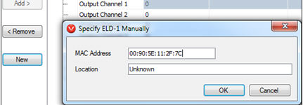
If Offline: Select the required amplifier channel and select New. The Specify ELD-1 Manually dialogue box will appear. Enter the ELD-1 MAC Address and Location. The MAC Address information can be found on the outside of the physical ELD-1 device.
When assigning an ELD-1 to an amplifier Zone configured for failover it is required that the same ELD-1 is assigned to each amplifier on the same channels. The Failover mode is required to be configured in the amplifier properties before multiple ELD-1’s can be assigned.
Multiple ELD-1 assignment can be achieved two ways. By manually adding the ELD-1 using the New button. If an ELD-1 has already been assigned to a channel then the assignment can be copied to the redundant channel by holding the 'ctrl' key and ‘dragging and dropping’ the ELD-1 to the redundant channel.
Channel Failover with a parallel speaker configuration would be configured as shown;
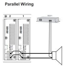
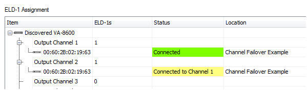
See Channel Failover section for wiring details.
Chassis Failover on a VA-8600 would be configured as shown;
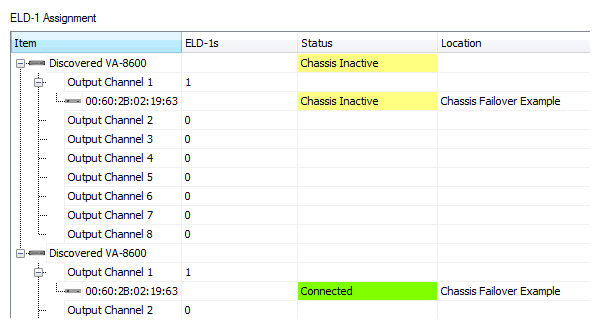
See Device Failover section for wiring details.