The Vocia Interface Module 16 (IM-16) is designed to supplement the Vocia LSI-16. The IM-16 offers an additional sixteen Control Inputs which can be configured in the Vocia software as Alarm, Fault or Reset inputs. An LSI-16e contains an IM-16 module by default.
All software configuration of the IM-16 is performed with the LSI-16 Dialog Windows.
Please review the IM-16 input wiring section to review supported wiring and interfacing.
Please refer to the IM-16 Manual for more details.
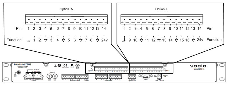
IM-16 pinouts on life safety interface 16 rear panel
| Pin | Option A Function |
Option B Function |
| 1 | Chassis Ground / Shield | Chassis Ground / Shield |
| 2 | Control Input 1 | Control Input 9 |
| 3 | Control Input 2 | Control Input 10 |
| 4 | Isolated Ground | Isolated Ground |
| 5 | Control Input 3 | Control Input 11 |
| 6 | Control Input 4 | Control Input 12 |
| 7 | Isolated Ground | Isolated Ground |
| 8 | Control Input 5 | Control Input 13 |
| 9 | Control Input 6 | Control Input 14 |
| 10 | Isolated Ground | Isolated Ground |
| 11 | Control Input 7 | Control Input 15 |
| 12 | Control Input 8 | Control Input 16 |
| 13 | Isolated Ground | Isolated Ground |
| 14 | 24V (60mA total across all inputs in Option slot A & B) | 24V (60mA total across all inputs in Option slot A & B) |
IM-16 Pinout Table
Both Chassis
Ground (![]() ) and Isolated
Ground (
) and Isolated
Ground (![]() ) are provided on the IM-16 connectors.
) are provided on the IM-16 connectors.
By default, all input circuits should be isolated with respect to the ground. Any external input connections must be logic referenced to the Isolated Ground. This configuration allows external equipment to be interconnected to the LSI-16 without ground current interaction between devices.
The IM-16 Chassis ground appears on a single terminal (Pin 1) on each of the two connector banks (‘Option A’ and ‘Option B’). This should only be used if circuit isolation is not required and should only be connected to the cable screen.
For ease of wiring each connector, every Control Input pair has an Isolated Ground connection adjacent to it however the Isolated grounds are all connected internally so any could be used.
The logic level of each input may be independently determined in the Vocia software to operate one of three ways. These are;
Please review the IM-16 Wiring Inputs section for physical wiring details.
The High Range logic inputs should be driven from a contact closure (relay or switch) in connected equipment The High range inputs expect to sense a voltage of 24V DC. A 24V Logic High Reference output voltage is provided by the IM-16 for this purpose.
Alternatively an external 24V reference may be used. If an external supply is used, the ground connection must be wired to the IM-16 Isolated Ground.