In addition to Channel-to-Channel Failover, all Vocia amplifiers support 1:1 amplifier chassis Failover (Device Failover). Each amplifier in a Failover pair is required to be the same model type. For example, a VA-2060 cannot Failover to VA-4030. A cable is required to be connected between the Failover link connections on the Failover amplifier pair. When configuring Device Failover, the amplifier channel Load Selection switches of the primary and redundant amplifiers must be set to physically use the same Impedance setting.
When device failover occurs, switching relays on the amplifier modules will physically break loudspeaker connections on the Primary Device and make connections on the Secondary Device. As a result, you can have two physical cable runs to each loudspeaker, one from the Primary Device and one from the corresponding output channel on the Secondary Device, or a single loudspeaker can be connected in parallel between two amplifier channels. Both methods will allow audio to continue to flow when device failover occurs. Refer to the wiring schematic below for both options.
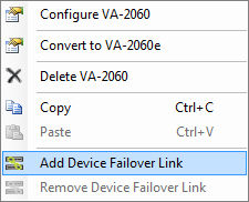
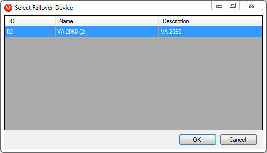
The Chassis Failover link functionality is activated by right clicking the Primary Failover device in the Layout window, then selecting Add Failover Link. This will open a Select Failover Device dialog that will display a list of matching amplifiers available for Failover in the project.
Select the desired device and it will become the Secondary Device in the Failover scenario.
 .
.
The two units will become a logical pair and the pairing is reflected in the Layout window. If the Primary Device experiences an Alarm condition it will automatically transfer control to the Secondary Device, which will continue to process and distribute audio, taking on all of the functions of the Primary Device.