This section is provided to aid in the use of the VA-8600 series amplifiers. Please see the VA-8600 Installation Manual for further information on installation of the device.

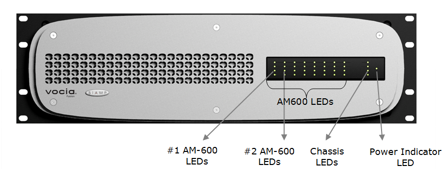
On the front panel, the VA-8600 has a single LED that indicates power and connectivity status:
Four LEDs located in the center of the front panel act as identifiers for each of the eight output channels (columns 1–8) and the chassis overall (column 9). These are useful for setting optimum output levels as well as monitoring the state of the amplifier and its channels. Each LED has four states: red, amber, green, and dark (not illuminated). Please see the table below for the signal mapping to each of the LEDs. Detailed metering of current output levels can be obtained in real time via the Vocia software interface.
Table 1. Channel LEDs
| LED Row | Label | Red | Amber | Green | Dark |
| 1 | AMP FAULT | Never | Flashing- Warning Solid- Fault | Never | No Amp Faults |
| 2 | ACTIVITY | Never | Configured and in standby* | Configured and active | Not configured |
| 3 | SIGNAL | Signal above clip threshold (>=-2dBFS) | Signal above peak but below clip threshold (>-6dBFS & <-3dBFS) | Signal above min. but below peak threshold (> -36dBFS & < -7dBFS) | Signal below min. threshold (<-36dBFS) |
| 4 | - | - | - | - | - |
Table 2. Chassis LEDs
| LED Row | Label | Red | Amber | Green | Dark |
| 1 | AMP FAULT | Never | Flashing- Warning Solid- Fault |
Never | No Amp Faults |
| 2 | ACTIVITY | Configuration Load Failure | Flashing - Not configured | Configured and active | Not configured |
| 3 | STATUS | POST Failure | Booting (flashing LED) | Boot succeeded | Did not boot |
| 4 | - | - | - | - | - |
*. Only applicable on amplifier modules configured for redundancy operation
**. Only applicable on amplifier chassis configured for redundancy operation

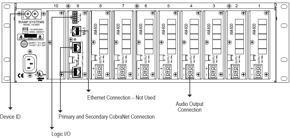
The VA-8600 has two RJ45 connectors located on the rear panel that enable redundant network wiring. The third RJ45 connector labeled “Ethernet” is not used in Vocia systems.
The RJ45 connectors utilize standard Ethernet cabling to interface the VA-8600 to the Vocia system via a managed network switch.
The connector provides two LEDs that indicate Ethernet link and network activity (see table below).
| Left LED | Right LED | Description |
| None | None | No power or data connectivity. Please check the Device power and network connection. |
| Amber | Flashing Green | Link established and CobraNet activity detected; the unit is acting as a CobraNet performer. |
| Flashing Amber | Flashing Green | Link established and CobraNet activity detected; the unit is operating as a CobraNet conductor. |
| Off | Flashing Green | Failover connection standing by in case the Primary connection fails. By default will be the right Hand socket (Secondary). |
| Flashing Amber | None | CobraNet fault. Check cabling and configuration for errors. |
Vocia supports one-to-one automatic amplifier Failover in case of fault. Failover is triggered by one of the following conditions:
Only faults (i.e. heatsink fault and channel fail fault) trigger the Failover mechanism. Warnings indicate abnormal system conditions that do not immediately impair audio and do not trigger the Failover mechanism.
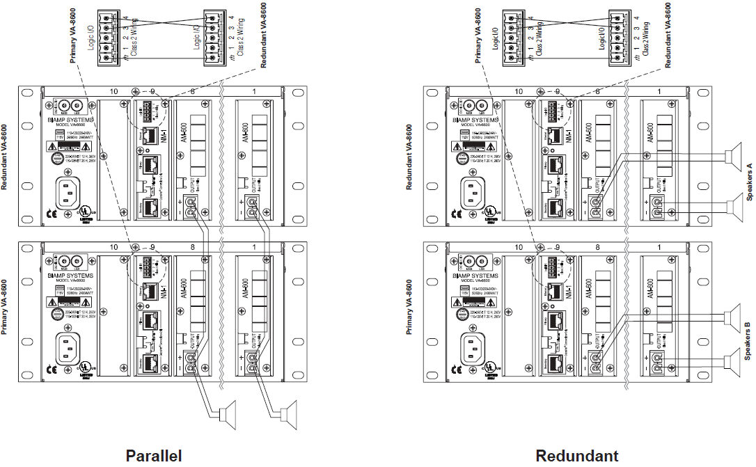
The redundant amplifier must have the same physical card and software configuration as the primary amplifier (i.e. amplifier module count, watts per module, load configuration). A wire Failover link cable (marked logic I/O) must be connected between the primary and the redundant amplifier as shown;

After replacing the faulty amplifier, a power cycle is required of both amplifiers to recover from the failover condition. The primary device will take control after the fail condition is cleared and the unit is re-powered. When a system is configured with Failover amplifiers, the primary amplifier will need to be powered up within 10 seconds of the secondary amplifier to allow the amplifiers to negotiate mastership correctly.
Wiring of the speaker circuits for device-to-device failover should be as follows;

In addition to entire amplifier Failover, Vocia supports channel-to-channel Failover, which is triggered by one of the following conditions:
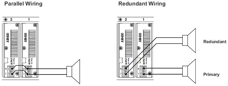
Wiring of speaker circuits for channel-to-channel failover should be as follows, the example shows a 1:1 channel failover configuration;

Note that the Device failover link is not required when using channel-to-channel failover.
The AM-600C monitors for a ground connection placed on either or both speaker wires. To prevent false ground fault readings the DC resistance to ground of speaker circuits must be 100kΩ or higher (either speaker wire to ground).
ELD-1's and PLD-1's are compatible with this device (note: PLD-2's are not). Refer to the relevant section for more information on using these devices in conjunction with this amplifier.