
This section is provided to aid in the use of the Vocia Output 4 enhanced (VO-4e). Please see the VO-4e Manual for further information on installation of the device.
The LED indicators on the front panel provide information and operational status and the output channels. The LED indicators are placed in blocks and read from left to right when looking at the front of the amplifier. Channel indication LEDs are grouped consecutively from left to right when looking at the front of the unit.
PoE A green LED indicator will illuminate when PoE power is applied to the unit.
Aux A green LED indicates that 24V DC supply is applied to the unit via either or both 24V Auxiliary power inputs.
Chassis Fault A yellow LED illuminates when a chassis fault has occurred.
Activity indicates the configuration status of the Device.
Status indicates the health of the device hardware.
Amp Fault -illuminates when an external amplifier fault has occurred. Follows the state of the Amp Fault Inputs on the rear of the unit. The VO-4e Channel Options section allows specifying whether the Fault Inputs are Active High or Low.
Activity -illuminates when the channel is configured
Signal -illuminates when the output channel is configured and passing audio

Network Connections - The CobraNet network connection is configured with the primary connector on the left and the secondary (redundant) connector on the right The primary and secondary CobraNet ports are provided to facilitate connection redundancy. Each connector has two associated LEDs that indicate Ethernet link and network activity (see table below).
| Left LED | Right LED | Description |
| None | None | No power or data connectivity. Please check the Device power and network connection. |
| Amber | Flashing Green | Link established and CobraNet activity detected; the unit is acting as a CobraNet performer. |
| Flashing Amber | Flashing Green | Link established and CobraNet activity detected; the unit is operating as a CobraNet conductor. |
| Off | Flashing Green | Failover connection standing by in case the Primary connection fails. By default will be the right Hand socket (Secondary). |
| Flashing Amber | None | CobraNet fault. Check cabling and configuration for errors. |
Auxiliary Power - allows the use of a dual 24V DC power input.
Device ID switches -The rotary ID switches allow the unit to be assigned a unique Device ID. The switches are in hexadecimal format. A Device ID must be assigned to the unit for correct operation.
Page Active Relay (PAR) – Each channel has a relay that will engage when paging is active in the channel at or above a priority specified for that PAR in Vocia software. Relay Normally Open (NO) and Normally Closed (NC) contacts are presented on 3.5mm plugable screw block connectors. Both NO and NC contacts can be used at the same time..
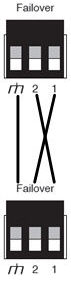
Failover -1:1 Channel and Device Failover is supported. The Failover connector facilitates redundant Device Failover only (Failover must be to another VO-4e unit). Wiring is ‘crossed’ as indicated below. Further details can be found in the Failover section.
ELD-1's are compatible with this device (note: PLD-1's and PLD-2's are not). Refer to the relevant section for more information on using these devices in conjunction with this amplifier.