The CI-1 & LSI-16(e) connection to a Fire Detection System can be complex. This page shows typical connection procedures that can be used however care should be taken to ensure the connections comply with specific code requirements.
Fault inputs allow the signaling of Faults from external devices that could affect Emergency operation of the Vocia system. These Fault signals are typically derived from contact closures located within the external devices. All Fault inputs are asserted by connecting the relevant pin to Isolated Ground. The UPS Fault, PSU Fault and EWS PSU Faults must be connected to 24V when non-asserted through a pull-up resistor. The Ethernet Fault input is pulled-up internally and does not need an external pull-up.
The VRef connection may be used as a voltage source for pull-ups on required Fault inputs. This output is current limited at 100mA. An external PSU can also be sourced for this voltage.
A Fault is introduced when the voltage present to the Fault Input transitions from High to Low. Low Level is considered 0-8VDC and High Level is considered 12-24VDC. There is Hysterisis in the circuit.
The resistors shown in the pull up circuits are present to ensure that the power supply used never sees a direct short. The resistors specified are common values for short to mid length runs. If long cable runs are present between the CI-1 and the monitored equipment the resistor value may need to be lessened. This can be checked by measuring the voltage present between the Fault Input and Ground and ensuring that the High to Low transition meets the voltage values listed above.
Refer to CI-1 and LSI-16 manuals for more information.
1. Terminating Unused Fault Inputs
If any Fault port is not used it MUST be terminated. This will indicate to the Vocia system that there is no Fault present. The Ethernet Fault connection is not monitored and does not require a monitor voltage.
2. Monitoring of Multiple Devices on a Single Fault Input
If more than one device needs to be monitored from a single Fault input the devices may be wired in parallel. The lines that require pull up resistors must still retain them. Resistor values shown are default values and may be required to change. More devices may be added to the parallel circuit as needed. Monitoring Contact shown In Non-Fault State.

3. Fault Monitoring With No Line Monitoring
The monitoring voltage and required load resistors are introduced on the CI-1 end of the system. Connecting the Fault Inputs in this manner will NOT register an open or short in the connecting wire as a Fault. In the wiring diagram below an external power supply could be used in place of the CI-1 Vref. Resistor values shown are default values and may be required to change. Monitoring Contact shown In Non-Fault State.

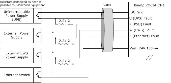
4. Fault and Line Monitoring
The monitoring voltage and required load resistors are introduced on the monitored equipment end of the system. Connecting the Fault Inputs in this manner will register an open or short in the connecting wire as a Fault. In the wiring diagram below an external power supply could be used in place of the CI-1 Vref. Resistor values shown are default values and may be required to change. Monitoring Contact shown In Non-Fault State.