This section is provided to aid in the use of the VI-6. Please see the VI-6 Hardware Manual for further information on installation of the device.
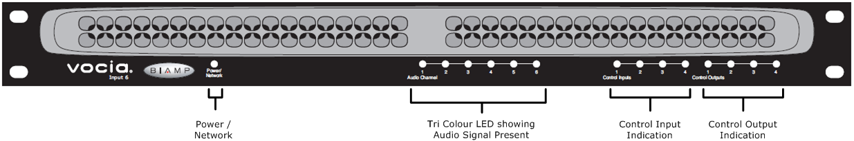
On the left of the front panel, the VI-6 has a single LED that indicates power and connectivity status:
Not illuminated The device is not powered.
Flashing green The unit is receiving power but not data, or the unit has not been configured correctly.
Solid green The unit is operational, has been configured and is receiving PoE.
Six LEDs located in the center of the front panel act as audio signal identifiers for the six input channels and are useful for setting optimum signal levels. Each LED has four states. Please see the table below for the signal mapping to each of the LEDs. Detailed metering of current output levels can be obtained in real time via the Vocia software interface.
| Red | Amber | Green | Dark |
| Signal above clip threshold > -2dbFS | Signal above nominal but below clip threshold > -18dBFS < -3dBFS | Signal above minimum but below nominal threshold > -48dBFS < -19dBFS | Signal below minimum threshold < -48dBFS |
The control LEDs signal the current state of the control I/Os. The first four are input status indicators, and the second four are output status indicators.
| Amber | Green | Dark |
| Relays are energized | > input threshold | Not active |
The VI-6 has one RJ45 connector located on the rear panel that utilizes standard Ethernet cabling to interface the VI-6 to the Vocia system via a managed switch. The RJ45 provides two LEDs that indicate Ethernet link and network activity.
| Left LED | Right LED | Description |
| None | None | No power or data connectivity. Please check the Device power and network connection. |
| Amber | Flashing Green | Link established and CobraNet activity detected; the unit is acting as a CobraNet performer (normal operation). |
| Flashing Amber | Flashing Green | Link established and CobraNet activity detected; the unit is operating as a CobraNet conductor (normal operation). |
| Flashing Amber | None | CobraNet fault. Check cabling and configuration for errors. |
The Control Outputs, labeled 1 through 4, are isolated, voltage-free, software-configurable relay outputs. The individual pins are labeled as follows:
(C): the common/ground pin
(NC): normally closed (connected to C when relay is not energized)
(NO): normally open (connected to C when relay is energized)
The Control Inputs are labeled as follows:
(Ground symbol): logic common/ground input pin
(1–4): individual logic inputs
(10V): 10V reference voltage (when used as a switch input, a switch must be connected between the input and logic common terminal)
Two sets of plug-in barrier strip and RCA connectors provide analog audio signal input. Inputs 1 through 4 are designed for line-level input. The RCA and plug-in barrier strip connectors are resistively summed internally so that a stereo source can be conveniently converted to mono audio. Inputs 5 and 6 are designed for microphone or line-level inputs and include phantom power. All plug-in barrier strip connectors should be wired from left to right as follows:
High
Low
Ground
The VI-6 has four Paging Ports on the rear of the unit which facilitate connection of either a Vocia Paging Stations Interface 1 (VPSI-1) or a Vocia Auxiliary Microphone 1 (VAM-1), or a combination of both. The Paging Ports when used in conjunction with these devices allow a balanced audio input, external Push-to-Talk and LED feedback of Zone and Paging states.
When the VI-6 audio input path is configured to use the Paging Ports the associated line inputs of the VI-6 will be disabled. The Audio Channel Signal Presence LEDs on the front of the VI-6 chassis will continue to operate when the input channel is configured for Paging. It will function as it normally would when configured as a Background or a User Input. The LEDs will function regardless of whether the associated ancillary paging devices PTT is pressed.
Refer to the Vocia Paging Stations Interface 1 (VPSI-1) or a Vocia Auxiliary Microphone 1 (VAM-1) section for more details on functionality and wiring schematics.