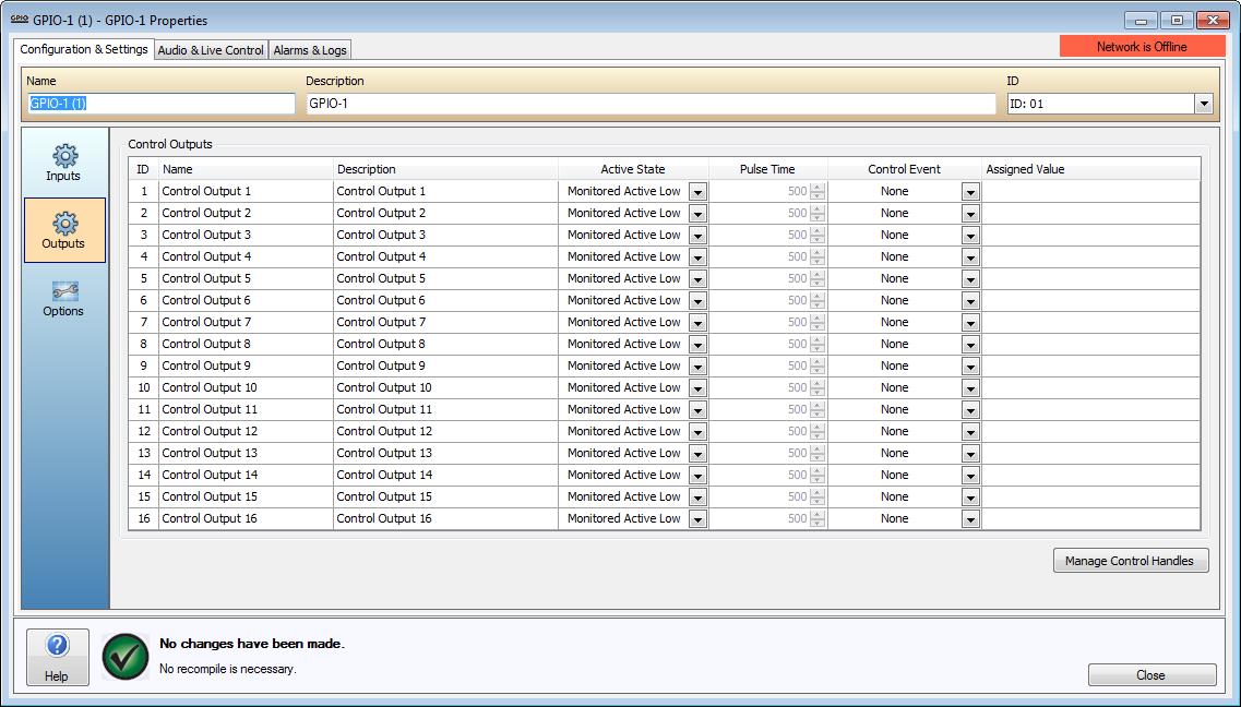
Sixteen Control Outputs are provided on the GPIO-1. Outputs are capable of being asserted by Control Event functions as specified in the software. See the GPIO-1 Hardware section for details on hardware functionality.
Outputs are discrete, meaning only one Control Output Event can be assigned to a physical Output at a time. The outputs will remain 0off unless a reference voltage is applied to VM connections. To facilitate this a 24V Ref out is available on the hardware. Please refer to the GPIO-1 Wiring Outputs for more details on the physical wiring requirements.
The Name and Description columns allow users to associate each of the four Input and Output channels with the physical input and output configuration of the device.
An Active State can be specified. This can be configured as a High, Low, Pulse High, Pulse Low, and Monitored Active Low. When Pulse High or Pulse Low are selected, the Pulse Time column will become available. The Pulse Time field allows the amount of time the output is asserted to be specified in milliseconds. Monitored Active Low selection will cause the GPIO to look for a high to low current transition to activate while connected to a monitored 24V circuit.
The Control Event field can be used to select a Paging Activity, Control Handle, Emergency Message, Emergency Indicator or Page Code Control Event.
The Assigned Value field can be used to configure additional options for the selected Control Event.
The following Control Output Events are supported;
Paging Activity - When a Page Code with a priority greater than or equal to a specified paging priority is playing in either the specified Output Channel or the specified Zone the output will be asserted.
Control Handle - Activated by the state of a Control Handle set via VTP or a physical Control Input. Control Inputs relate to either on the GPIO-1 itself or another device.
Emergency Message - Indicates when a specific Emergency Message is being played in a specific Emergency Zone. The type of event can also be used to indicate when an Emergency Zone has been muted by the LSI-16/LSI-16e.
Emergency Indicator - Indicates the current state of any one of the Emergency Faults (General Alarm, General Fault, System Fault, System Power, Protection Fault, Transmission Path Fault).
Page Code - When a specific Page Code is playing in a specific Zone.
NOTE: You must have an LSI-16e in the same World as the GPIO-1 if a Control Output is configured as either an Emergency Indicator or Emergency Message indicator.
For further details on Control Output Events, please refer to the Control Output Events section.
Zone Assignment to Emergency Messages is performed in the Emergency Messages section of the World Properties dialog window. Emergency Messages can be imported using the Audio File Manager.