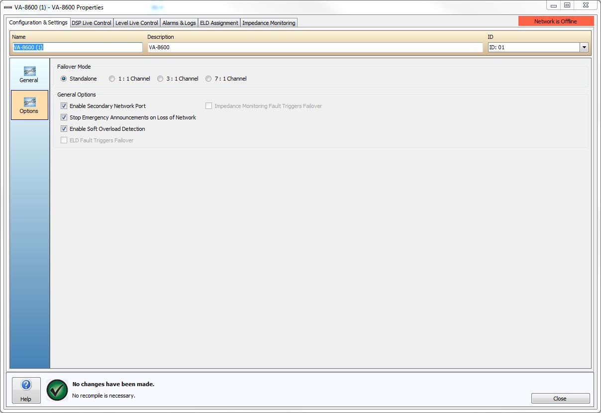
Enabling channel failover for the VA-8600 provides a means of establishing an automatic channel failover mode using two adjacent channels within a single VA-8600. The VA-8600 supports 1-to-1, 3-to-1 and 7-to-1 channel failover mode (with the addition of a failover module in slot 10 of the amplifier required for 3:1 and 7:1 failover mode). See VFOM-1 Hardware for more details. Depending on the failover mode radio-button selection on the Options page the failover selection boxes in the General section will update automatically. The DSP Live Control and Level Live Control dialogs will also update to reflect the failover configuration.
For channel failover the two designated channels become a logical pair and are referred to as Primary Channel and Secondary Channel. If the Primary Channel experiences a channel Alarm, it will automatically transfer control to the Secondary Channel, which will continue to process and distribute audio, taking on all of the functions of the Primary Channel. To revert back to normal operation the amplifier must be power-cycled or reset via the software VA-8600 Test tab (only shown when the software is Online and the amplifier configured).
In 1:1, 3:1 or 7:1 failover mode, if any of the Primary Channels experiences a Channel Alarm, the system will automatically transfer control to the Secondary Channel, which will continue to process and distribute audio, taking on all of the functions of the Primary Channel. As is the case with Device Failover, the Secondary Channel will not be able to be controlled independently from the Primary Channel.

When Channel Failover occurs, switching relays on the AM-600 amplifier modules will physically break loudspeaker connections on the Primary Channel and make connections on the Secondary Channel.
As a result, you can have two physical cable runs to the loudspeaker, one from the Primary Channel and one from the Secondary Channel, or a single run to the loudspeaker but paralleled across both amplifier outputs so that audio will continue to flow when channel failover occurs. In the case of 3:1 or 7:1 failover this redundant cabling would wire through the fail over module. See the VA-8600 Hardware section for more information on circuit wiring.
Test Failover
Once a Failover setting has been enacted through the software when the Vocia Software is Online and the amplifier configured a tab labeled Test will appear in the dialog window. The Test tab can be used to both generate failover triggers and to reset Primary and Secondary VA-8600s to their original default state. It will also show the Control State (Low or High) of each output channel on a PARM-1 if installed.

Is enabled by default. If only one network connection is required the Primary CobraNet network connection must be used. Disabling the secondary network port will disable the secondary Network connection and stop the Alarms reported due to the Secondary CobraNet connection not being available.
Is used to specify on what happens to any Emergency Messages already being played by the device upon complete loss of network communications.
Short circuit alarms may be shown falsely if the impedance of the output is too low. Disable this option if short circuit alarms are being reported but the speaker line is known to be good.
An ELD-1 or a PLD-1 can be used to trigger failover when a fault is reported from an end of line device for that channel. This option will be disabled unless failover mode has been enabled.
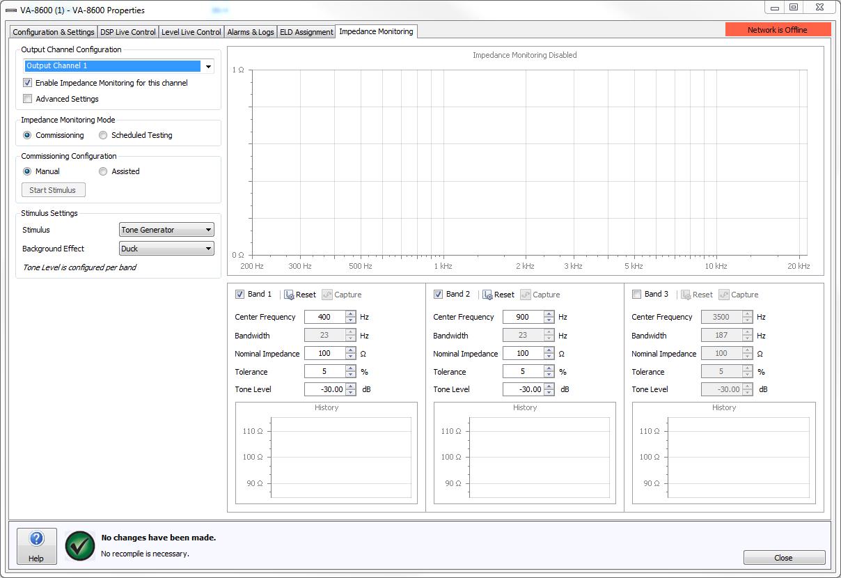
An Impedance Monitoring fault can be used to trigger failover. This option will be disabled unless failover mode has been enabled.