This section is provided to aid in the use of the LSI-16. Please see the LSI-16 Manual for further information on installation of the device.
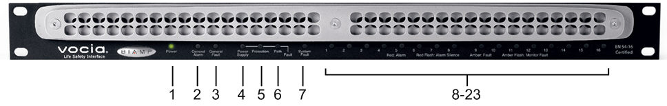
The LSI-16 features twenty-three LEDs on the front plate (from left to right):
The first LED on the left of the front panel indicates power status
1. Not illuminated: The device is not powered.
2. Solid green: The unit is operational. Power is being supplied from either the main or PoE supply.
This LED will illuminate red if the LSI-16 receives an alarm signal from an external emergency detection system (e.g. a fire alarm system) via the Alarm inputs to the LSI-16. This LED indicates the general alarm state.
1.Solid red - The LSI-16 has received an alarm signal from an external emergency detection system (e.g. fire alarm system).
2.Flashing red - The LSI-16 has received a General Alarm silence from an external emergency detection system (e.g. fire alarm system).
This LED will illuminate in yellow if there is a Fault in the life safety announcement system connected to the LSI-16 that does not affect the possible delivery of an Emergency Message.
This LED will illuminate in yellow the LSI-16 is operating on a PoE supply but the main 24V supply fails or an external power supply fault is signaled to the LSI-16.
This LED will illuminate yellow if a system amplifier channel fails and this failure does not prevent an Emergency Zone voice announcement. Note: failures that do affect Emergency Zone voice announcements will result in a System Fault.
This LED will illuminate in yellow if a fault in the transmission path is detected. The path integrity is tested from microphone capsule to end of loudspeaker lines if optional Vocia End of Line Device 1 (ELD-1) units are fitted at the end of the loudspeaker lines. If a PLD device detects errors on the speaker line it will also report as a Path Fault.
This LED indicates the integrity of the system:
1. Flashing yellow -The unit has a fault that may prevent the reliable operation of life safety announcement functions.
2. Not illuminated -The unit is operational without any faults that may prevent reliable operation of life safety announcement functions.
Because it indicates a potentially serious condition, the presence of a System Fault extinguishes indicators for PSU, Path and Protection faults so as to focus attention on the primary fault. However, individual PSU, Path and Protection faults are still shown in the system software and signaled to individual Fault outputs as described below.
The LSI-16 will always power up in the system Fault condition. Manual intervention is required to take the LSI-16 out of this condition. Note: this power up condition does not prevent Emergency Zone voice announcements provided that the system is operating reliably.
These two groups of LEDs indicate Zone and Alarm state functionality. The indications are dependent on whether an IM-16 option board has been installed.
1. If no option slot board is installed these LEDs will remain inactive.
2. If an IM-16 option board is installed the front panel LEDs will behaving in the following manner;
Solid Red: An Alarm is active on the associated input.
Flashing Red: An Alarm in the system has been silenced
Solid Amber: A Fault is active on the associated input.
Flashing Amber: An input configured as “high range - monitored” exhibits a monitoring fault.
3. If the LSI-16 has had an IM-16 option board installed it becomes an LSI-16e which will allow it to be configured in GPIO-1 mode if desired. The LSI-16 with an IM-16 installed should be designated as an LSI-16e within the project file. Designating an LSI-16 as an LSI-16e allows a third mode of operation for the front panel indicators which can then be assigned in the LSI-16e GPIO-1 Indicators section to perform a different role. The indicators can now be used to summarize the inputs states and monitoring fault conditions of one or more (up to 5) GPIO-1's per LSI-16e LED indicator. Refer to the GPIO-1 Fault State Indication on an LSI-16e section for more detail on the front panel indicator behavior in this mode.

Please refer to the LSI-16 manual for further details on any of the information below. The above image shows a LSI-16 with IM-16 module installed.
The LSI-16 has two RJ45 connectors located on the rear panel that enable redundant network wiring for connectivity and secondary power supply. If communication fails on either Ethernet port, the LSI-16 reports a fault. For this reason, both Ethernet ports must be connected to the Vocia network, and both should be supplied from a PoE source for auxiliary power.
The RJ45 connectors utilize standard Ethernet cabling to interface the LSI-16 to the Vocia system via a managed network switch.
The RJ45 connector provides two LEDs that indicate Ethernet link and network activity. An LED either side of the RJ-45 socket will illuminate to indicate PoE power is being received.
| Left LED | Right LED | Description |
| None | None | No power or data connectivity. Please check the Device power and network connection. |
| Amber | Flashing Green | Link established and CobraNet activity detected; the unit is acting as a CobraNet performer. |
| Flashing Amber | Flashing Green | Link established and CobraNet activity detected; the unit is operating as a CobraNet conductor. |
| Off | Flashing Green | Failover connection standing by in case the Primary connection fails. By default will be the right Hand socket (Secondary). |
| Flashing Amber | None | CobraNet fault. Check cabling and configuration for errors. |
Two black five-position connectors are located next to the rotary switches. These are predominately used for Monitored Outputs to external lamps or sounders. Individual output channels are labeled 1 through 8 (see table below for connector assignments). One connection is configured for use as both an input and an output (1) and one as an input (2).
| Marking | Function |
| Ground | |
| 1 | Sounder Output/ Silence Input |
| 2 | System Fault Reset Input |
| 3 | Voice Alarm Active |
| 4 | General Fault |
| 5 | PSU Fault |
| 6 | Protection Fault |
| 7 | Path Fault |
| 8 | External Supply Over-voltage Monitor |
| 10V | 10 Volt Out |
The Monitored Outputs will sink current (pull low) when active (see the Specifications section of the LSI-16 manual for more details). The desired load (lamp, LED, etc.) must be connected between the output terminal and a positive voltage reference.
These outputs are monitored and can detect open- or short-circuits in external connections. This feature facilitates compliance with voice evacuation standards. A load must be connected between each output and the positive voltage source. If any output on terminals 1 through 8 is unused, the output must be connected through an external resistor to the positive side of the voltage source (either 10V Out or user-supplied external source). The value of each resistor should be 22kΩ to ensure proper functionality. An internally derived 10V source is provided at the 10V Out terminal; however, the total current available from this pin is limited to 100mA. This voltage source may be used for external devices provided the total load is less than 100mA.
For higher-current devices, a user-supplied external voltage source of up to 35V may be used, with the negative side connected to the pin. Due to monitoring constraints, it is impossible to use both the internal 10V source and an external source. For monitoring purposes, the positive side of the voltage source (either 10V Out or user-supplied external source) must be connected to the External Supply Over-voltage Monitor (terminal 8), as well as supplying voltage to external devices.
For more information please see the LSI-16 User Manual.
Two five-position plug-in barrier strip connectors provide control input connections. Eight separate channels plus two ground pins are provided (see table below for connector assignments). Control inputs are fully isolated from all connections in the LSI-16.
| Marking | Function |
| Ground | |
| 1 | PSU Fault (contact closure indicates a PSU Fault) |
| 2 | Ethernet Fault |
| 3 | Voice Alarm Silence from CIE (common for all zones) |
| 4 | Voice Alarm Reset from CIE (common for all zones) |
| Ground | |
| 5 | Emergency Detection System Alarm 1 |
| 6 | Emergency Detection System Alarm 2 |
| 7 | Emergency Detection System Alarm 3 |
| 8 | Emergency Detection System Alarm 4 |
Control Inputs 1 and 2
To activate an input, it must be connected to an external circuit that returns to either of the two pins. The resistance of this circuit must be less than 4kΩ.
Control Inputs 3 to 8
These inputs must be permanently connected to an external circuit that returns to either of the two pins. The resistance of this circuit must be between 1kΩ and 4kΩ. To activate an input, pull the input to a voltage between 12 and 24V.
PSU Fault
This input may be derived from the primary 24V power supply to indicate to the LSI-16 if there is a fault in the power supply.
This may be required for standards compliance.
Ethernet Fault
This input can be derived from an Ethernet switch to monitor the Ethernet network connection between the LSI-16 and amplifier. This may be required for standards compliance.
Voice Alarm Silence from CIE (fire alarm system)
This input is a signal from the CIE (fire alarm system) that will mute emergency messages in all emergency zones.
Voice Alarm Reset from CIE (fire alarm system)
This input is a signal from the CIE (fire alarm system) that will reset emergency messages in all emergency zones.
Emergency Detection System Alarm
These four inputs are used to connect to the fire alarm control and indicating equipment (CIE) and notify the LSI-16 that an alarm has occurred on a particular zone. Four such zone inputs may be connected. Additional zone inputs will be available through the option module. When an alarm is detected, the Vocia system will enter Emergency Mode as configured for that input. During Emergency Mode, some or all of the Vocia system will cease normal operation and operate as programmed for the emergency.
Option Slot
The option slot allows for the addition of an IM-16 module. This provides 16 configurable Alarm of Fault Inputs. An LSI-16e has this fitted as standard.
System Fault Relay Connection
This relay is activated when the LSI-16 is fully operational. It may be used for informing external devices about the LSI-16’s operating conditions or sounding an alarm that indicates the LSI-16 is not functioning correctly.
RS-232
This port may be used for RS-232 communication with the LSI-16 using LSI-VTP
24V DC Connector and LED
This is the primary (main) power supply input for the LSI-16 and as such must be fed from a suitable source of 24V DC capable of 15 watts (625mA). The 24V DC supply has to be sourced separately. In typical installations, this supply will be provided from a power supply compliant with local norms and required standards (typically battery-backed). The adjacent LED indicates the presence of power.