The U, P and A commands will be the only commands available until the remote LSI-16 VTP user has been authorized.
Command |
Argument |
U |
Username |
The U command will be used to supply a Username in order to gain access to the LSI-16 TCP/IP interface. This command must be executed prior to sending the P command. The U, P and A commands will be only ones available until the remote LSI VTP user has been authorized.
If connecting Via RS-232 no authentication is required
Command |
Argument |
P |
Password |
The P command will be used to supply a password in order to gain access to the LSI-16 RS-232 or TCP/IP interface. This command must be executed prior to sending the A command. The U, P and A commands will be only ones available until the remote LSI VTP user has been authorized.
If connecting Via RS-232 no authentication is required
Command |
Argument |
A |
Not needed |
The A command will be used to authorize a LSI-16 VTP User with the LSI-16 and gain access to the protected VTP control via the LSI-16 VTP interface. It is necessary to first send a Username and password using the U and P commands respectively. The U, P and A commands will be only ones available until the remote LSI-16 VTP user has been authorized. Responses will be of the form specified in XML Responses.
If connecting Via RS-232 no authentication is required
Example Sequence with XML Responses |
### Welcome to the Vocia LSI
U admin <?xml version="1.0"?><Status Command="U"><State>STATE_OK</State></Status>
P admin <?xml version="1.0"?><Status Command="P"><State>STATE_OK</State></Status>
A <?xml version="1.0"?><Status Command="A"><State>AUTH_SUCCESS</State></Status> |
Connection |
Command |
Argument |
State |
TCP |
H |
connection id ( 1, 2, 3, 4 ) |
token then next token |
RS-232 |
H |
connection id (0) |
token then next token |
The H command is used by the LSI-16 to ascertain the integrity of a RS-232 or TCP/IP connection. A token is passed between the LSI-16 VTP user and the LSI-16. This token is an unsigned integer that the LSI-16 compares with a stored copy of the last token transmitted. If these match then the connection will be reported as good. If a matching token is not received by the LSI-16 within 15 seconds of the last good token received the connection will be declared bad and a path fault generated. A valid handshake command should be sent to the LSI-16 every five seconds.
For TCP and RS-232 Connections the remote LSI-16 VTP user will be required to supply a connection ID. For TCP connections this is a numerical value (1-4) and should correspond with one of the four enabled monitored TCP Connections configured in the LSI-16 General Settings tab. For RS-232 connections this is always the number 0. Using RS-232 requires the use of the H handshake command.
If handshake communications are lost, a Path Fault will be indicated on the front panel of the LSI-16, and the LSI-16 Alarms and Log tab will show a bad transmission path alarm. If connected via TCP/IP an LSI-16 TCP/IP transmission path will indicate as BAD. If connected via RS-232 a LSI-16 RS-232 transmission path will indicate as BAD.
The TCP connectionid is a numerical value of 1 to 4.
The RS-232 connectionid is always a value of 0.
The Token will always start at 0 (zero).
The LSI-16 responds with the next token to be used for the next handshake. This needs to be sent as the new token.
Example Sequence with XML Responses |
H 1 0 <?xml version="1.0"?><Status Command="H"><State>STATE_OK</State><Token>1<Token></Status>
H 1 1 <?xml version="1.0"?><Status Command="H"><State>STATE_OK</State><Token>2<Token></Status>
H 1 2 <?xml version="1.0"?><Status Command="H"><State>STATE_OK</State><Token>3<Token></Status> |
Command |
Argument |
Argument |
I |
Input number |
state |
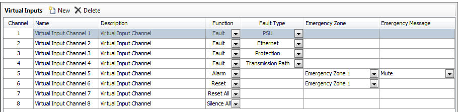
The I command will be used by the LSI-16 VTP User to set the state of a virtual input. Virtual inputs behave much like the inputs of an IM-16. They can be configured in the Vocia GUI in the LSI-16 Virtual Inputs tab to perform one of the following functions:
Disabled
Alarm
Fault
Reset
Reset All
Silence All
Fault inputs are level sensitive. If the input is ON then the fault is active. If the input is OFF the fault is inactive. All other virtual input types are positive edge triggered – they will enable on a low to high transition. So a command to set the input to ON will enable the associated function (the zone virtual input will go active), whereas a command to turn the input OFF will be ignored.
To enable Virtual Input 1 the command will be: I 1 1
To disable Virtual Input 1 the command will be: I 1 0
The Virtual Input Channel Number is the channel number as listed in the Vocia GUI under LSI-16 properties/ Virtual Inputs.
State sets the specified input ON (state = 1) or OFF (state = 0). The response will be:
<?xml version="1.0"?><Status Command= “I”> <State> STATE_OK</State></Status>
Example Sequence with XML Responses |
I 1 0 <?xml version="1.0"?><Status Command="I"><State>STATE_OK</State></Status>
I 1 0 <?xml version="1.0"?><Status Command="I"><State>STATE_OK</State></Status> |
Command |
Argument |
Delimiter |
Argument |
Argument |
G |
Lowest Input number |
- |
Highest Input number |
state |
The G command can be used to set the state of multiple virtual inputs at once (maximum 50 inputs per 'G' command). Virtual inputs behave much like the inputs of an IM-16. They can be configured in the Vocia GUI in the LSI-16 Virtual Inputs tab to perform one of the following functions:
Disabled
Alarm
Fault
Reset
Reset All
Silence All
Fault inputs are level sensitive. If the input is ON then the fault is active. If the input is OFF the fault is inactive. All other virtual input types are positive edge triggered – they will enable on a low to high transition. So a command to set the input to ON will enable the associated function (the Zone virtual input will go active), whereas a command to turn the input OFF will be ignored.
To enable Virtual Inputs 20 through 30, the command will be: G 20-30 1
To disable Virtual Inputs 5 to 10, command will be: G 5-10 0
Note that the delimiter character ("-") is always required to seperate a range of indexes.
The Virtual Input Channel Number is the channel number as listed in the Vocia GUI under LSI-16 properties/ Virtual Inputs.
State sets the specified input ON (state = 1) or OFF (state = 0). The response will be:
<?xml version="1.0"?><Status Command= “G”> <State> STATE_OK</State></Status>
Example Sequence with XML Responses |
G 10-30 0 <?xml version="1.0"?><Status Command="G"><State>STATE_OK</State></Status>
G 50-55 1 <?xml version="1.0"?><Status Command="G"><State>STATE_OK</State></Status> |
The R S command will allow the System Fault alarm to be reset if the LSI-16(e) has been configured to support remote resetting of system fault via VTP.
In a Master-Slave Emergency system, if this command is issued to the Master LSI-16(e) and the “Reset on Master Triggers Reset on All Slaves” option is enabled then all Slave LSI-16(e)’s will also have their System Fault reset.
Command |
Argument |
R S |
Not needed |
The F S command can be used to obtain the current fault status from the LSI-16(e).
| The XML Response if successful will be |
<?xml version=\"1.0\"?> <Reset Command="R S"> <State>STATE_OK</State> </Reset> |
| The XML Response if there is an error will be |
<?xml version=\"1.0\"?> <Reset Command="R S"> <State>STATE_FAULT</State> </Reset> |
Command |
Argument |
Z Z |
zone id |
The Z Z command will be used to obtain the current status of a particular emergency zone. The Q Z Command can be used to get a listing of current configured Emergency Zones.
The status of a zone can be Inactive, Muted, or Announcing. If the zone is in the Announcing state, the response will contain the name of the announcement currently playing in that zone.
The Zone Id will be the emergency zone id number assigned in the Vocia configuration. One Emergency Zone can be specified at a time.
The ZoneState tag will return the default state of the zone as defined by the LSI-16. This state does not incorporate emergency paging in any form. It will report as Inactive, Muted, Announcing
Inactive : Normal mode paging, background music and emergency pages will be heard in the zone.
Muted : All normal mode paging, background music and emergency recorded announcements are muted. Only emergency pages will be allowed.
Announcing: The emergency zone will continually play an emergency announcement in a looping fashion. All normal mode paging, background music will be muted. Emergency pages take priority.
The ZoneAvailable tag indicates if there are available operational output channels for the Emergency Zone. Supported Output devices include the VA-8600, VA-2060, VA-4030 and VO-4e.
Will be either
Yes - At least one output channel with the specified Emergency Zone is available.
No - There are no operational emergency output channels available.
The <ZoneMessage> tag is only present if the zone state is Announcing.
| XML response |
| <?xml version="1.0"?><ZoneStatus Command= “Z”><State> STATE_OK</State><Zone Id=zone><ZoneState>Zone state</ ZoneState><ZoneAvailable>Yes/No</ZoneAvailable><ZoneMessage>”Message Name”</ ZoneMessage></ZoneStatus> |
Command |
Argument |
Z A |
not needed |
The Z A command will be used to obtain the current status of a all emergency zones in a World. The status of a zone can be Inactive, Muted, or Announcing. If the zone is in the Announcing state, the response will contain the name of the announcement currently playing in that zone.
The Zone Id will be the emergency zone id number assigned in the Vocia configuration.
The ZoneState tag will return the default state of the zone as defined by the LSI-16. This state does not incorporate emergency paging in any form. It will report as Inactive, Muted, Announcing
Inactive : Normal mode paging, background music and emergency pages will be heard in the zone.
Muted : All normal mode paging, background music and emergency recorded announcements are muted. Only emergency pages will be allowed.
Announcing: The emergency zone will continually play an emergency announcement in a looping fashion. All normal mode paging, background music will be muted. Emergency pages take priority.
The ZoneAvailable tag indicates if there are available operational output channels for the Emergency Zone. Supported Output devices include the VA-8600, VA-2060, VA-4030 and VO-4e.
Will be either
Yes - At least one output channel with the specified Emergency Zone is available.
No - There are no operational emergency output channels available.
The <ZoneMessage> tag is only present if the zone state is Announcing.
| The XML Response will be |
<?xml version="1.0"?><ZoneStatus Command= “A”><State> STATE_OK</State><Zones count=number of zones> <Zone Id=zone1><ZoneState>Zone1 state</ ZoneState > <ZoneAvailable>Yes/No</ ZoneAvailable > <ZoneMessage>”Message Name”</ ZoneMessage></Zone> <Zone Id=zone2><ZoneState>Zone2 state</ ZoneState > <ZoneAvailable>Yes/No</ ZoneAvailable > <ZoneMessage>”Message Name”</ ZoneMessage></Zone> <Zone Id=zoneM><ZoneState>ZoneM state</ ZoneState > <ZoneAvailable>Yes/No</ ZoneAvailable > <ZoneMessage>”Message Name”</ ZoneMessage></Zone> <Zone Id=zoneN><ZoneState>ZoneN state</ ZoneState > <ZoneAvailable>Yes/No</ ZoneAvailable > <ZoneMessage>”Message Name”</ ZoneMessage></Zone></Zones</ZoneStatus> |
The Q command is used to query aspects of the LSI-16’s configuration. Commands are provided to display a list of all emergency mode devices and a list of all emergency zones.
Command |
Argument |
Q D |
not needed |
The response will be:
<?xml version="1.0"?><Query Command= “D”><State> STATE_OK</State>
<Devices count=”Number of devices”>
<Device type="Type" id=”Id”>”TypeString”:”Id”</Device>
<Device type="Type" id=”Id”>” TypeString”:”Id”</Device>
...
<Device type="Type" id=”Id”>” TypeString”:”Id”</Device>
<Device type="Type" id=”Id”>” TypeString”:”Id”</Device>
</Devices></Query>
Valid "Type" and "TypeString" are as follows:
Note: |
|
Device Type |
Device Name |
Valid ID Range |
2 |
WS-4 |
01 - FF |
4 |
WS-10 |
01 - FF |
8 |
LSI-16 |
01 - FF |
10 |
VO-4e |
01 - FF |
12 |
VA-8600 |
01 - FF |
14 |
GPIO-1 |
01 - FF |
17 |
VA-4030(e) |
01 - FF |
18 |
VA-2060(e) |
01 - FF |
32 |
VI-8 |
01 - FF |
33 |
VOIP-1 |
01 - FF |
34 |
POTS-1 |
01 - FF |
35 |
VA-8150CV |
01 - FF |
36 |
VA-4300CV |
01 - FF |
Command |
Argument |
Q I |
InputID |
InputID is a numerical value of the Virtual Input. This can be obtained using the ‘Q L’ Command. A response with the details of a specific virtual input configuration will be provided. The response format will depend on how the virtual Input is configured.
Virtual Input configured as a Fault Input:
The response will be:
<?xml version="1.0"?> <Query Command= “I”><State> STATE_OK</State>
< VirtualInputDetail id=”Input Id”><Name>”Input name string”</ Name >
<Description>”Input description string”</ Description>
<Function>”Fault”</Function>
<FaultType>”Input Fault Type”</ FaultType >
</VirtualInputDetail ></Query>
The input fault type can be one of the following:
PSU
Ethernet
Protection
Transmission Path
The response will be:
<?xml version="1.0"?><Query Command= “I”><State> STATE_OK</State>
< VirtualInputDetail id=”Input Id”><Name>”Input name string”</ Name >
<Description>”Input description string”</ Description>
<Function>”Alarm”</Function> <Zone id=”Id”>”Zone name string”</Zone>
<ZoneMessage>”Zone message string”</ ZoneMessage >
</VirtualInputDetail ></Query>
The zone message string will be the Virtual Input label as configured in the Vocia software or:
Mute - indicating that this input will mute the associated zone.
Unknown - indicating a configuration parsing error.
The response will be:
<?xml version="1.0"?><Query Command= “I”><State> STATE_OK</State>
< VirtualInputDetail id=”Input Id”><Name>”Input name string”</ Name >
<Description>”Input description string”</ Description>
<Function>”Reset”</Function>
<Zone id=”Id”>”Zone name string”</Zone>
</VirtualInputDetail ></Query>
Virtual Input configured as an All Zone Silence Input:
The response will be:
<?xml version="1.0"?> <Query Command= “I”><State> STATE_OK</State>
< VirtualInputDetail id=”Input Id”><Name>”Input name string”</ Name >
<Description>”Input description string”</ Description>
<Function>”All silence”</Function>
</VirtualInputDetail ></Query>
Virtual Input configured as a All Zone Reset Input:
The response will be:
<?xml version="1.0"?><Query Command= “I”><State> STATE_OK</State>
< VirtualInputDetail id=”Input Id”><Name>”Input name string”</ Name >
<Description>”Input description string”</ Description>
<Function>”All reset”</Function>
</VirtualInputDetail ></Query>
Example Sequence with XML Responses |
### Welcome to the Vocia LSI U admin <?xml version="1.0"?><Status Command="U"><State>STATE_OK</State></Status>
P admin <?xml version="1.0"?><Status Command="P"><State>STATE_OK</State></Status>
A <?xml version="1.0"?><Status Command="A"><State>AUTH_SUCCESS</State></Status>
Q I 1 <?xml version="1.0"?><Query Command="I"><State>STATE_OK</State><VirtualInputDetail id="1"> <Name>Virtual Input Channel 1</Name><Description>Virtual Input Channel</Description> <Function>Fault</Function><FaultType>PSU</FaultType></VirtualInputDetail></Query>
Q I 2 <?xml version="1.0"?><Query Command="I"><State>STATE_OK</State><VirtualInputDetail id="2"> <Name>Virtual Input Channel 2</Name><Description>Virtual Input Channel</Description> <Function>Fault</Function><FaultType>Ethernet</FaultType></VirtualInputDetail></Query>
Q I 3 <?xml version="1.0"?><Query Command="I"><State>STATE_OK</State><VirtualInputDetail id="3"> <Name>Virtual Input Channel 3</Name><Description>Virtual Input Channel</Description> <Function>Fault</Function><FaultType>Protection</FaultType></VirtualInputDetail></Query>
Q I 4 <?xml version="1.0"?><Query Command="I"><State>STATE_OK</State><VirtualInputDetail id="4"> <Name>Virtual Input Channel 4</Name><Description>Virtual Input Channel</Description> <Function>Fault</Function><FaultType>TransmissionPath</FaultType></VirtualInputDetail></Query>
Q I 5 <?xml version="1.0"?><Query Command="I"><State>STATE_OK</State><VirtualInputDetail id="5"> <Name>Virtual Input Channel 5</Name><Description>Virtual Input Channel</Description> <Function>Alarm</Function><Zone id="1">Emergency Zone 1</Zone> <ZoneMessage>Mute</ZoneMessage></VirtualInputDetail></Query>
Q I 6 <?xml version="1.0"?><Query Command="I"><State>STATE_OK</State><VirtualInputDetail id="6"> <Name>Virtual Input Channel 6</Name><Description>Virtual Input Channel</Description> <Function>Reset</Function><Zone id="1">Emergency Zone 1</Zone></VirtualInputDetail></Query>
Q I 7 <?xml version="1.0"?><Query Command="I"><State>STATE_OK</State><VirtualInputDetail id="7"> <Name>Virtual Input Channel 7</Name><Description>Virtual Input Channel</Description> <Function>All reset</Function></VirtualInputDetail></Query>
Q I 8 <?xml version="1.0"?><Query Command="I"><State>STATE_OK</State><VirtualInputDetail id="8"> <Name>Virtual Input Channel 8</Name><Description>Virtual Input Channel</Description> <Function>All silence</Function></VirtualInputDetail></Query> |
Command |
Argument |
Q L |
not needed |
The response will be:
<?xml version="1.0"?>
<Query Command= “L”><State> STATE_OK</State>
<VirtualInputs count=”Number of inputs”>
<VirtualInput id=”Id”>”Input name string”</VirtualInput>
<VirtualInput id=”Id”>”Input name string”</VirtualInput>
...
<VirtualInput id=”Id”>”Input name string”</VirtualInput>
</ VirtualInputs></Query>
The input “Id” is a 1 based input number.
Command |
Argument |
Q Z |
not needed |
The response will be:
<?xml version="1.0"?><Query Command= “Z”><State> STATE_OK</State>
<Zones count=”Number of zones”>
<Zones id=”Id”>”Zone name string”</Zone>
<Zones id=”Id”>”Zone name string”</Zone>
...
<Zones id=”Id”>”Zone name string”</Zone>
<Zones id=”Id”>”Zone name string”</Zone>
</Zones></Query>
The zone “Id” is the zone number.
Example Sequence with XML Responses |
QZ <?xml version="1.0"?><Query Command="Z"><State>STATE_OK</State><Zones count="3"> <Zone id="1">Emergency Zone 1</Zone> <Zone id="2">Emergency Zone 2</Zone> <Zone id="3">Emergency Zone 3</Zone> </Zones></Query> |
The F command will be used to obtain the current fault status from the LSI-16. Commands are provided to display a summary list of emergency faults, device specific faults all current faults.
Command |
Argument |
F S |
not needed |
Example Sequence with XML Responses |
F S <?xml version="1.0"?><Faults Command="S"><State>STATE_OK</State><EmergencyFaults > <Fault type="Voice Alarm Active">STATE_OK</Fault> <Fault type="System Fault">STATE_FAULT</Fault> <Fault type="General Fault">STATE_FAULT</Fault> <Fault type="VACIE Power Fault">STATE_FAULT</Fault> <Fault type="Protection Fault">STATE_OK</Fault> <Fault type="Transmission Path Fault">STATE_OK</Fault> <Fault type="System Available">STATE_OK</Fault> <Fault type="System Configuration">STATE_OK</Fault> <Fault type="Multiple LSI-16 Masters">STATE_OK</Fault> <Fault type="Audio Path Fault">STATE_OK</Fault> <Fault type="Fault Sounder Active">STATE_FAULT</Fault> <Fault type="Software Fault">STATE_OK</Fault> <Fault type="Device Memory Failure">STATE_OK</Fault> <Fault type="Device Offline">STATE_OK</Fault> <Fault type="Unknown Device Detected">STATE_OK</Fault> <Fault type="Excessive Device Restarts">STATE_OK</Fault> <Fault type="Emergency Detection System Fault">STATE_FAULT</Fault> <Fault type="LSI-16 Master Restart">STATE_FAULT</Fault> <Fault type="Network Fault">STATE_OK</Fault> </EmergencyFaults></Faults> |
Command |
Argument |
Argument |
F D |
DevType |
Devid |
The F D command will return a fault listing for all Emergency Devices excluding the LSI-16(e)
The nature of the response will depend on the specified device and will include all information provided by the device to the LSI-16.
The response will be:
<?xml version="1.0"?>
<Faults Command= “D”><State> STATE_OK</State>
<DeviceFaults type=" Type" Id= "Id">
<Fault type="System Fault">STATE_FAULT</Fault>
<Fault type="General Fault">STATE_FAULT</Fault>
<Fault type="Protection Fault">STATE_OK</Fault>
<Fault type="System Configuration">STATE_OK</Fault>
<Fault type="Audio Path Fault">STATE_FAULT</Fault>
<Fault type="Device Memory Failure">STATE_OK</Fault>
<Fault type="Device Offline">STATE_OK</Fault>
</DeviceFaults></Faults>
Valid type and id strings are as follows:
Note: |
|
Device Type |
Device Name |
Valid ID Range |
2 |
WS-4 |
01 - FF |
4 |
WS-10 |
01 - FF |
8 |
LSI-16 |
01 - FF |
10 |
VO-4e |
01 - FF |
12 |
VA-8600 |
01 - FF |
14 |
GPIO-1 |
01 - FF |
17 |
VA-4030(e) |
01 - FF |
18 |
VA-2060(e) |
01 - FF |
32 |
VI-8 |
01 - FF |
33 |
VOIP-1 |
01 - FF |
34 |
POTS-1 |
01 - FF |
35 |
VA-8150CV |
01 - FF |
36 |
VA-4300CV |
01 - FF |
Example Sequence with XML Responses |
F D 18 1 <?xml version="1.0"?><Faults Command="D"><State>STATE_OK</State> <DeviceFaults type="18" id="01"> <Fault type="Device Offline">STATE_OK</Fault> <Fault type="Audio input 1">STATE_OK</Fault> <Fault type="Audio input 2">STATE_OK</Fault> <Fault type="Audio output 1">STATE_FAULT</Fault> <Fault type="Audio output 2">STATE_OK</Fault> <Fault type="System Fault">STATE_OK</Fault> <Fault type="General Fault">STATE_OK</Fault> <Fault type="Protection Fault">STATE_OK</Fault> <Fault type="System Configuration">STATE_OK</Fault> <Fault type="LSI-16 Master Timeout">STATE_OK</Fault> <Fault type="Audio Path Fault">STATE_FAULT</Fault> <Fault type="Device Memory Failure">STATE_OK</Fault> </DeviceFaults> </Faults> |
Command |
Argument |
F F |
not needed |
This includes any active emergency faults and a summary of active device faults. The device fault summary is intended to indicate that there is a fault associated with a particular device without providing any detail. An “F D” command could then be used to find out which particular fault had been detected. Only devices that have faults will be listed.
The response will be:
<?xml version="1.0"?>
<Faults Command= “F”><State> STATE_OK</State><EmergencyFaults>
<Fault type="General Fault">STATE_FAULT</Fault>
...
<Fault type="Transmission Path Fault">STATE_FAULT</Fault></EmergencyFaults>
<DeviceFaults type=" Type " Id= Id ><Fault type="Summary">STATE_FAULT</Fault></DeviceFaults>
<DeviceFaults type=" Type " Id= Id ><Fault type="Summary">STATE_FAULT</Fault></DeviceFaults>
...
<DeviceFaults type=" Type " Id= Id ><Fault type="Summary">STATE_FAULT</Fault></DeviceFaults>
</Faults>
Valid type and type strings are as follows:
Note: |
|
Device Type |
Device Name |
Valid ID Range |
2 |
WS-4 |
01 - FF |
4 |
WS-10 |
01 - FF |
8 |
LSI-16 |
01 - FF |
10 |
VO-4e |
01 - FF |
12 |
VA-8600 |
01 - FF |
14 |
GPIO-1 |
01 - FF |
17 |
VA-4030(e) |
01 - FF |
18 |
VA-2060(e) |
01 - FF |
32 |
VI-8 |
01 - FF |
33 |
VOIP-1 |
01 - FF |
34 |
POTS-1 |
01 - FF |
35 |
VA-8150CV |
01 - FF |
36 |
VA-4300CV |
01 - FF |
Example Sequence with XML Responses |
F F <?xml version="1.0"?><Faults Command="F"><State>STATE_OK</State><EmergencyFaults> <Fault type="General Fault">STATE_FAULT</Fault> <Fault type="Transmission Path Fault">STATE_FAULT</Fault> <Fault type="System Available">STATE_FAULT</Fault> <Fault type="Audio Path Fault">STATE_FAULT</Fault> <Fault type="Fault Sounder Active">STATE_FAULT</Fault> </EmergencyFaults> <DeviceFaults type="18" id="01"><Fault type="Summary">STATE_FAULT</Fault> </DeviceFaults> </Faults> |
Command |
Argument |
F A |
not needed |
This command operates as a virtual 'local Silence'. So performs the same way as physically pressing the 'Local Silence' on a CI-1 front panel.
The response will be:
<?xml version="1.0"?>
<Faults Command=“A”>
<State>STATE_OK</State></Faults>
The "@" command is used to relay a specific VTP command to an emergency paging station or LSI-16(e) in the local World, via the LSI-16(e) hosting the current connection.
| Command | Argument |
| @ | Dev_Type Dev_ID Command |
Device Type (Dev_Type) is '2' for an EWS-4, '4' for an EWS-10 and '8' for an LSI-16(e).
Device ID (Dev_ID) is the unique identifier the device has been assigned formatted as a hex number. Valid ID range is 01 - FF.
Command is a PS VTP string as specified. See the PS VTP Glossary for available commands.
The response will be:
<?xml version="1.0"?>
<VTPRelay Command="@">
<Device type=”2” id=”05”>EWS-4:05</Device>
<State>STATE_OK</State>
<Response>[Response From EWS-4/EWS-10]</Response>
</VTPRelay>
Where [Response From EWS-4/EWS-10] is the PS-VTP response from the remote device.
A <State>STATE_FAULT</State> response will be returned if the device specified is unable to be communicated with.
Example Sequence with XML Responses |
@ 2 66 Q L
<?xml version="1.0"?> <VTPRelay Command="@"> <Device type="2" id="66">EWS-4:66</Device> <State>STATE_OK</State> <Response> <Query Command="L"><State>STATE_OK</State><Pagecodes count="2"> <Pagecode id="1">Emergency Code 1</Pagecode> <Pagecode id="2">Emergency Code 2</Pagecode> </Pagecodes></Query> </Response> </VTPRelay> |
Note: It is not possible to use the relay command to send a command to another LSI-16(e) that asks it to relay the command to a third device.